Sure, here is the first part of the article:
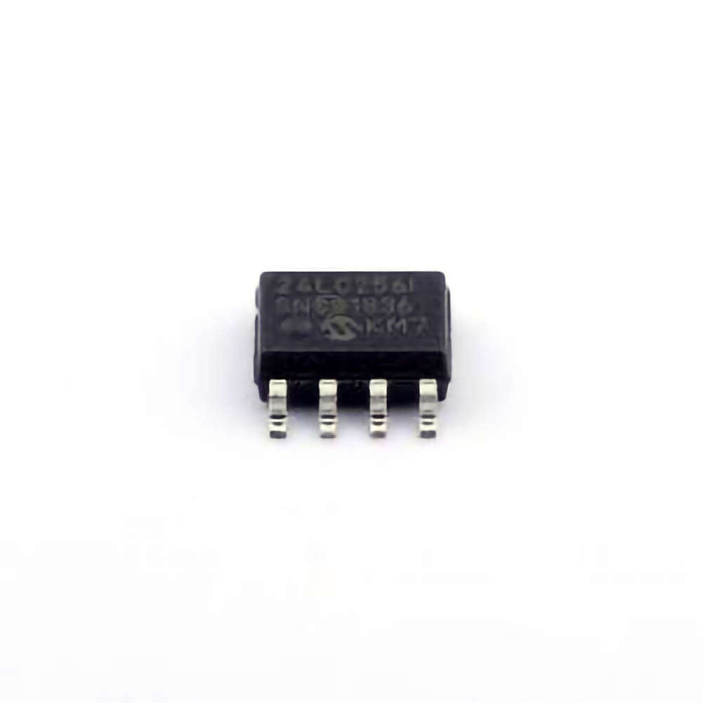
The 24LC256-I/SN is a widely used EEPROM ( Electrical ly Erasable Programmable Read-Only Memory ) in various electronic applications. This article explores common troubleshooting techniques and solutions for users working with the 24LC256-I/SN. Whether you're dealing with Communication issues, programming failures, or unexpected behavior, we break down the challenges and offer practical fixes.
24LC256-I/SN, EEPROM troubleshooting, I2C communication, memory corruption, EEPROM programming errors, 24LC256 solutions, EEPROM repair, I2C bus issues, microcontroller, EEPROM read/write failure
Introduction to 24LC256-I/SN EEPROM
The 24LC256-I/SN is a 256 Kbit (32 Kbyte) I2C-compatible EEPROM chip from Microchip Technology. It is widely used in applications requiring non-volatile memory storage, such as firmware storage, configuration data retention, and other similar uses in microcontroller-based systems. The I2C interface makes it a popular choice due to its simplicity and ability to communicate over two wires.
However, like all electronic components, the 24LC256-I/SN can encounter issues in various scenarios. From communication failures to read/write errors, understanding the common problems and their solutions is critical to ensuring smooth operation in your project.
In this first part, we’ll cover some of the most common troubleshooting scenarios and solutions for the 24LC256-I/SN EEPROM.
1. I2C Communication Failure
I2C is a widely used communication protocol, but it is not immune to issues. Problems with communication between a microcontroller (MCU) and the 24LC256-I/SN EEPROM can result from several factors. Common signs include failed reads, writes, or a complete lack of response from the EEPROM.
Common Causes:
Incorrect wiring or connection: One of the most frequent causes of I2C communication failures is improper wiring. Make sure that the SDA (data) and SCL (clock) lines are correctly connected between the microcontroller and the EEPROM.
Addressing issues: The 24LC256-I/SN has a 7-bit I2C address. The default address is typically 0x50, but it can vary depending on how the chip's address pins are configured. If the addressing is incorrect, the EEPROM will not respond to the MCU.
Power supply problems: If the EEPROM is not receiving a stable power supply (typically 3.3V or 5V, depending on the version), communication failures may occur.
Bus conflicts: The I2C bus can experience conflicts if multiple devices are using the same address or if there are other electrical issues (e.g., too much capacitance on the bus, improper pull-up resistors).
Solutions:
Verify the connections: Double-check the wiring for SDA, SCL, and VCC, ensuring that they are properly connected to the corresponding pins on the microcontroller.
Check the I2C address: If the EEPROM is not responding to the default address, refer to the datasheet to confirm the correct address based on your configuration (e.g., pull-up or pull-down on address pins).
Use pull-up resistors: Ensure that the SDA and SCL lines are equipped with appropriate pull-up resistors. For most I2C applications, 4.7kΩ resistors are commonly used, but this can depend on the bus capacitance and speed requirements.
Test with a logic analyzer: If you're still experiencing issues, using a logic analyzer can help identify where the communication fails. It will allow you to see whether the clock and data lines are properly transmitting signals.
2. Write Failures or Corruption of Data
Another common issue with the 24LC256-I/SN is when data write operations either fail or become corrupted. This can manifest as improper data being stored or the EEPROM rejecting write requests altogether.
Common Causes:
Write cycle time: The EEPROM requires a specific amount of time to complete each write operation. If the microcontroller sends subsequent write commands before the previous one has finished, the EEPROM may fail to complete the write operation.
Write protect pin (WP): The WP pin, when held low, disables write operations to the EEPROM. If this pin is unintentionally connected to ground or not properly configured, the EEPROM will not allow writes.
Power-down during write: If the system experiences a power loss or reset while writing to the EEPROM, the data may become corrupted. This is particularly an issue in low-voltage or unstable power systems.
Overwriting protected regions: The 24LC256-I/SN includes a mechanism to protect certain memory regions from being accidentally written over. If you try to write to a protected area, the operation will fail.
Solutions:
Respect write cycle times: Ensure that your code waits for the completion of one write operation before initiating another. According to the datasheet, the typical write cycle time is about 5 ms, but this can vary depending on the operating conditions (such as voltage levels and temperature).
Check the WP pin: Ensure that the WP (write protect) pin is correctly configured. If you need to allow write operations, the WP pin should be connected to a logic-high voltage (typically VCC) to enable writing.
Use an external power supply monitor: If your application is prone to power instability, consider adding a capacitor for power filtering or a power monitor to ensure that the EEPROM is not interrupted during a write cycle.
Ensure no writes to protected areas: The 24LC256-I/SN has dedicated memory blocks that are protected from write operations. Make sure you are not trying to write to these reserved areas.
3. Inconsistent or Incorrect Data Retrieval
Sometimes, when reading from the EEPROM, you might receive inconsistent or incorrect data. This could be due to a variety of reasons, such as poor signal integrity, faulty I2C communication, or even issues with how the data is being interpreted by the microcontroller.
Common Causes:
Signal degradation: I2C signals can degrade over long distances or at higher speeds. This can lead to incorrect data being transmitted or read.
Improper read timing: The 24LC256-I/SN requires the read operation to be properly timed. If there is a delay or the read command is sent too quickly after a write, the data might not be correctly retrieved.
Incorrect page addressing: The 24LC256-I/SN is organized in pages, and when performing a read, the starting address needs to be correctly set within the correct page boundaries. If not, data from an unintended location might be read.
Solutions:
Use appropriate wiring lengths: Try to keep the SDA and SCL lines as short as possible to minimize signal degradation. If using longer wires, consider using stronger pull-up resistors or reducing the I2C clock speed.
Check read timing: Implement a small delay after each write before initiating a read, allowing the EEPROM to settle into a consistent state.
Ensure correct addressing: When performing a read, make sure to send the correct address, including the page and byte locations. Refer to the datasheet to understand the memory organization and avoid cross-page reads.
4. Power-On Reset and Initialization Issues
At times, the 24LC256-I/SN may fail to initialize correctly after power-up, leading to issues like corrupted data or failed communication.
Common Causes:
Unstable power-on state: If the VCC or GND pins are not properly stabilized during power-up, the EEPROM may not initialize correctly.
Improper startup sequence: The EEPROM requires certain conditions to be met during initialization. If the MCU does not send the correct initialization sequence (e.g., setting up the I2C bus, sending a device address), the EEPROM may fail to communicate.
Solutions:
Ensure stable power supply: Use a stable power supply with adequate decoupling capacitors to prevent fluctuations during power-up.
Follow initialization sequence: Implement a robust startup sequence in your firmware to ensure that the EEPROM is properly initialized before any read or write operations are attempted.
Part 2 will continue with more detailed solutions and additional troubleshooting advice, including handling read/write timeouts, data retention issues, and using the EEPROM in more advanced applications.
If you are looking for more information on commonly used Electronic Components Models or about Electronic Components Product Catalog datasheets, compile all purchasing and CAD information into one place.
Partnering with an electronic components supplier sets your team up for success, ensuring the design, production, and procurement processes are quality and error-free.


