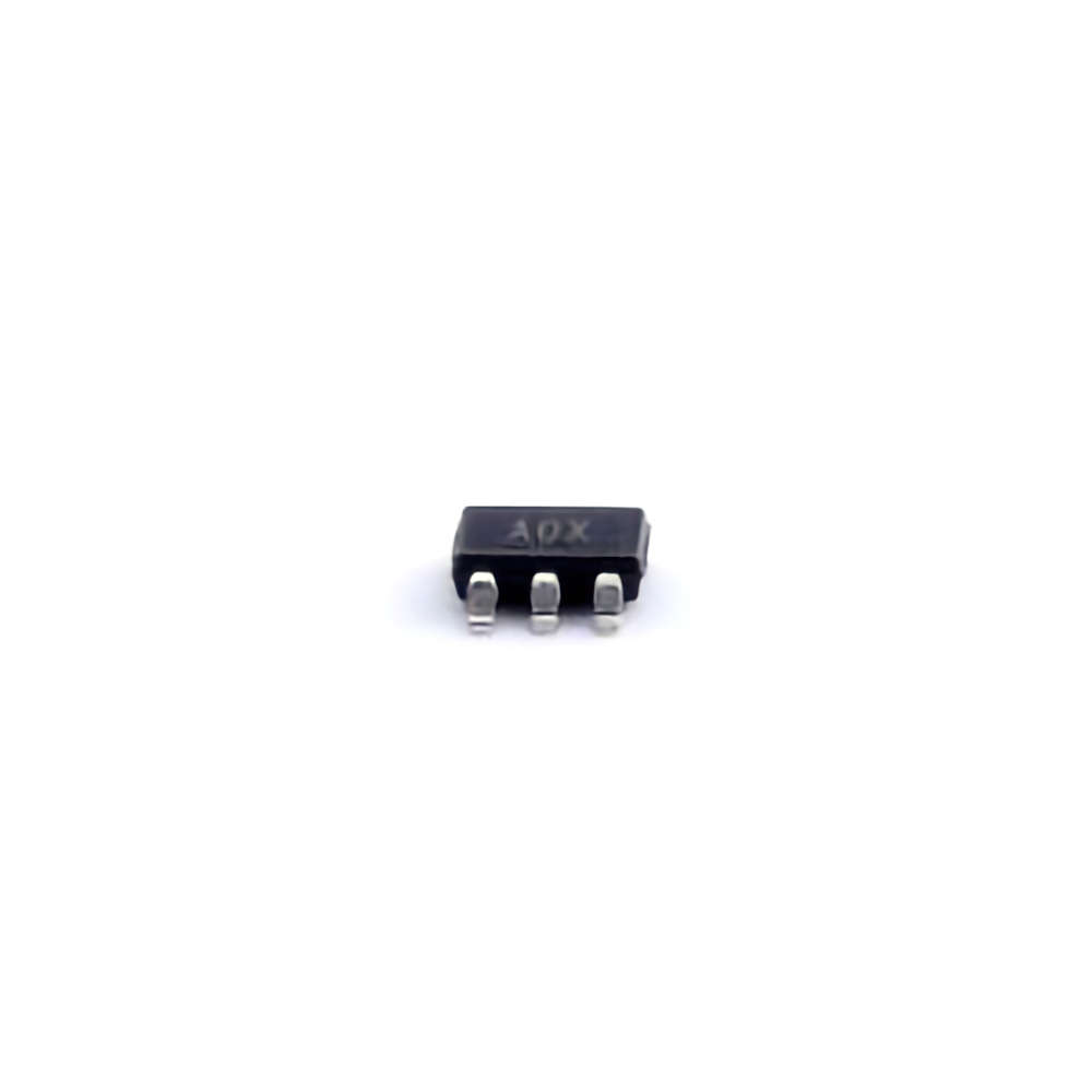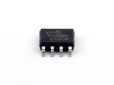
This article dives deep into common troubleshooting tips and solutions for the AD8603AUJZ-REEL7 operational amplifier, offering valuable insights for engineers and designers to resolve performance issues efficiently. By understanding the typical problems encountered with this low-noise, rail-to-rail operational amplifier, users can optimize their designs and avoid costly mistakes in their circuits.
Understanding the AD8603AUJZ-REEL7 and Common Issues
Introduction
The AD8603AUJZ-REEL7 is a high-performance, low-noise, rail-to-rail operational amplifier (op-amp) designed for precision applications. With its wide bandwidth, low offset voltage, and high input impedance, it’s commonly used in sensitive analog circuits where performance and reliability are critical. However, even the best components can encounter issues during integration into a circuit. In this article, we will explore common troubleshooting problems and solutions associated with the AD8603AUJZ-REEL7 to help engineers achieve optimal results.
1. Power Supply and Grounding Issues
One of the most frequent causes of malfunction in operational amplifier circuits is improper power supply or grounding. The AD8603AUJZ-REEL7 is designed to operate from a single supply voltage (2.7V to 36V) or dual supply (±1.35V to ±18V). Ensuring that the voltage supply is within the recommended range is essential for the op-amp’s proper functionality.
Common Power Supply Issues:
Inadequate or fluctuating power supply: If the supply voltage is unstable or too low, the op-amp may fail to operate correctly, resulting in signal distortion or complete failure of the circuit.
Incorrect voltage reference: For circuits requiring precise reference voltages, such as in Sensor applications, a poorly chosen reference voltage can lead to inaccurate readings or signal drift.
Solution:
Always use a stable, regulated power supply within the recommended voltage range for the AD8603AUJZ-REEL7.
If the circuit requires a specific reference voltage, ensure it is carefully designed and buffered to prevent drift.
Decouple the power supply with proper bypass capacitor s (e.g., 0.1µF and 10µF ceramic capacitors) near the op-amp’s power pins to filter out noise and stabilize the supply.
2. Input Bias Current and Offset Voltage Issues
The AD8603AUJZ-REEL7 boasts a low input bias current (typically 1pA) and low input offset voltage (typically 25µV), making it ideal for precision applications. However, these parameters can still cause issues in certain designs, especially if the input impedance is very high.
Common Input Issues:
High input impedance: When interfacing the op-amp with high-impedance sensors or networks, the small bias current may generate voltage drops across external resistors, leading to offset errors.
Input offset voltage drift: Changes in temperature or supply voltage can cause offset voltage to drift, affecting the accuracy of the signal processing.
Solution:
Use low-impedance input sources or design input buffers with lower impedance to reduce the effects of bias currents.
In designs where precision is critical, consider adding offset voltage correction circuitry or a compensation capacitor to stabilize the offset voltage over temperature variations.
3. Noise and Stability Problems
Although the AD8603AUJZ-REEL7 is a low-noise op-amp with a typical noise density of 2.5nV/√Hz at 1kHz, some circuits may still experience unwanted noise or instability due to improper layout or external interference.
Common Noise and Stability Issues:
Power supply noise: External noise on the power supply rails can be coupled into the op-amp’s output, especially if the power supply is not adequately decoupled.
Poor PCB layout: Long traces, insufficient grounding, or poor power distribution can introduce parasitic inductance and capacitance, degrading performance and causing instability, especially at high frequencies.
Solution:
Ensure that the PCB layout follows best practices for high-precision analog designs. Use a solid ground plane, minimize the length of signal traces, and avoid routing sensitive signal paths near noisy components.
Implement additional bypassing and filtering at the power pins to reduce supply noise. For sensitive applications, consider using separate power supplies for analog and digital sections to further reduce noise coupling.
4. Saturation and Output Clipping
In certain designs, the AD8603AUJZ-REEL7 may experience saturation or output clipping, which occurs when the op-amp’s output voltage exceeds its output swing capability. This issue is particularly common in applications with rail-to-rail output configurations.
Common Clipping Issues:
Over-driving the op-amp: When the input signal is too large or the gain is too high, the output may attempt to drive beyond the supply voltage limits, resulting in clipping.
Incorrect feedback network design: In some cases, feedback networks may cause the op-amp to reach its output limits under specific conditions.
Solution:
Make sure that the input signals and the gain setting are within the linear operating range of the op-amp. Avoid driving the op-amp with signals that exceed the recommended input voltage range.
Review the feedback and resistor network to ensure they do not create conditions that force the op-amp into saturation.
5. Temperature Sensitivity and Compensation
Like many op-amps, the AD8603AUJZ-REEL7’s performance can be affected by temperature variations. In high-precision applications, temperature-induced drift can be a significant issue.
Common Temperature Issues:
Offset voltage drift with temperature: While the AD8603AUJZ-REEL7 features low offset voltage, the offset can still change with temperature, leading to inaccurate results.
Thermal runaway or instability: In extreme cases, high temperatures can lead to thermal runaway, where the op-amp’s internal characteristics degrade, resulting in instability or failure.
Solution:
If temperature sensitivity is a concern, use precision resistors with low temperature coefficients in the feedback and input network.
For critical applications, select an op-amp with better temperature stability or include active temperature compensation circuits to maintain accuracy across a wide temperature range.
Advanced Troubleshooting and Circuit Optimization
6. Compensation for High-Frequency Noise and Instability
While the AD8603AUJZ-REEL7 is designed for low-noise operation, high-frequency noise can still be problematic in some designs. High-frequency instability and oscillations can arise, particularly when the op-amp is used in high-gain configurations or with capacitive loads.
Common High-Frequency Noise Issues:
Oscillations and ringing: High gain or capacitive loading on the op-amp’s output can cause oscillations, especially if the op-amp is not compensated for these loads.
Insufficient bandwidth: In some designs, especially at higher frequencies, the op-amp may not have sufficient bandwidth to handle the signals without distortion.
Solution:
Use appropriate compensation techniques, such as adding a small capacitor (typically in the range of 10pF to 100pF) between the op-amp’s output and inverting input to stabilize the circuit.
Ensure that the load presented to the op-amp is not excessively capacitive. In some cases, adding a series resistor (e.g., 10Ω to 100Ω) between the op-amp’s output and the load can help dampen oscillations.
7. Layout and PCB Design Optimization
An often overlooked yet crucial factor in troubleshooting the AD8603AUJZ-REEL7 is the design and layout of the PCB. Poor PCB layout can introduce noise, reduce signal integrity, and affect the op-amp’s performance.
Common Layout Issues:
Signal trace routing: Running signal traces near high-current or noisy components can induce electromagnetic interference ( EMI ) into sensitive analog signals.
Grounding problems: A poor or shared ground connection can introduce noise and cause incorrect operation of the op-amp, especially in high-precision designs.
Solution:
Implement a solid, continuous ground plane to reduce noise and provide a stable reference for the op-amp’s operation.
Route high-speed or high-impedance signals away from noisy components or power rails. Keep signal traces as short as possible, and use differential routing where applicable.
8. Aging and Long-Term Stability
While the AD8603AUJZ-REEL7 is built for long-term reliability, any component can experience aging effects that affect performance. This is especially true in circuits that operate in extreme environments or are subjected to constant stress.
Common Aging Issues:
Drift in offset voltage or bias current: Over time, components like resistors or capacitors in the feedback loop may drift, causing a gradual increase in the op-amp’s offset voltage or bias current.
Degradation of packaging or connections: Poor solder joints or degraded component leads can cause intermittent failures or unstable behavior in the op-amp.
Solution:
Use high-quality, stable components in the feedback and input networks to minimize drift over time.
Inspect and maintain the integrity of solder joints and connections, especially in high-reliability applications.
9. Addressing Common Application-Specific Issues
Different applications of the AD8603AUJZ-REEL7 may require specific troubleshooting approaches. Below, we discuss some common applications and the related troubleshooting considerations.
Sensor Interface:
Problem: Interfacing with high-impedance sensors can lead to errors due to input bias current.
Solution: Use a low-pass filter or buffer to minimize the effect of input bias currents.
Analog-to-Digital Conversion (ADC) Input:
Problem: Signal distortion or noise issues can occur when the op-amp is used as a buffer before an ADC.
Solution: Implement proper filtering and use a low-noise power supply to minimize noise interference in ADC systems.
Conclusion
By following the troubleshooting steps and design recommendations outlined in this article, engineers and designers can effectively address common problems encountered when using the AD8603AUJZ-REEL7 operational amplifier. From power supply issues to temperature sensitivity and high-frequency stability, understanding the root causes of these challenges is crucial for achieving optimal performance. With careful attention to circuit design, PCB layout, and component selection, users can maximize the potential of this exceptional op-amp in their applications.
If you are looking for more information on commonly used Electronic Components Models or about Electronic Components Product Catalog datasheets, compile all purchasing and CAD information into one place.
Partnering with an electronic components supplier sets your team up for success, ensuring the design, production, and procurement processes are quality and error-free.


