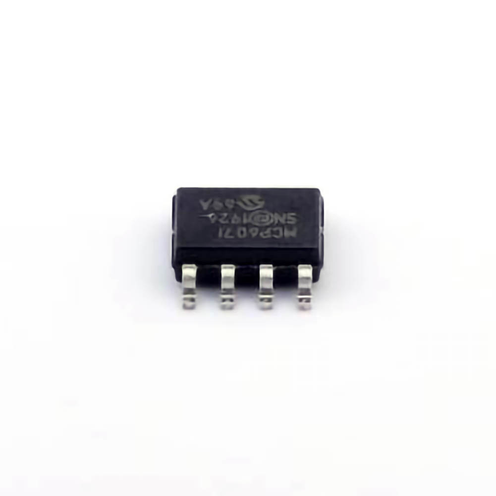
The MCP607T-I/SN operational amplifier (op-amp) is widely used in various electronic systems for signal processing. Despite its robust design, users may encounter common issues in circuit implementations. This article provides in-depth troubleshooting tips and practical solutions to help engineers and technicians resolve issues effectively, ensuring optimal performance of the MCP607T-I/SN op-amp in their applications.
MCP607T-I/SN, troubleshooting, operational amplifier, op-amp issues, MCP607 troubleshooting, op-amp solutions, electronics troubleshooting, MCP607 operational amplifier, amplifier circuit issues
Understanding the MCP607T-I/SN and Common Issues
The MCP607T-I/SN is a dual-channel, low- Power operational amplifier from Microchip Technology, designed for precision applications. It features a rail-to-rail input/output range and offers high input impedance, low offset voltage, and low noise operation, making it ideal for various low-power and portable electronic devices. However, even the most robust components can experience problems in real-world applications.
Overview of MCP607T-I/SN Features
Before diving into troubleshooting, it is essential to understand the core features of the MCP607T-I/SN. This op-amp operates with a wide supply voltage range, typically from 2.7V to 5.5V, and boasts a slew rate of 0.3V/µs, which is sufficient for many precision applications. It is known for its low quiescent current, which reduces power consumption, an important feature in battery-operated designs.
Despite its reliability, there are some common issues that engineers face when working with the MCP607T-I/SN op-amp. These problems often arise from improper usage or misunderstandings of the op-amp's limitations, such as supply voltage mismatches, incorrect grounding, or insufficient bypass capacitor s. Let's explore these common problems and how to resolve them.
1. Incorrect Power Supply Voltage
One of the most common issues faced when using the MCP607T-I/SN is improper power supply voltage. This op-amp is designed to operate within a voltage range of 2.7V to 5.5V. Exceeding this range, whether by over-voltage or under-voltage, can lead to erratic behavior, such as output saturation, malfunction, or even permanent damage to the internal circuitry.
Solution:
Check the power supply voltage: Ensure that the voltage supplied to the MCP607T-I/SN lies within the specified range of 2.7V to 5.5V. Using a multimeter or oscilloscope to verify the supply voltage under operating conditions is essential.
Use a regulated power supply: A regulated power source will provide stable voltage to the op-amp, preventing any voltage fluctuations that may cause issues.
Verify the input voltage range: In addition to the supply voltage, ensure that any input signals are within the recommended voltage range of the op-amp to prevent incorrect behavior.
2. Power Supply Decoupling Issues
In many designs, engineers might overlook the importance of decoupling capacitors when powering the MCP607T-I/SN. These capacitors help filter out high-frequency noise and provide a stable voltage supply, which is crucial for the optimal performance of the op-amp.
Solution:
Add bypass capacitors: Place a 0.1µF ceramic capacitor close to the power pins of the MCP607T-I/SN. This helps filter out high-frequency noise and transient voltage spikes that might affect the op-amp’s performance.
Use a larger bulk capacitor: In some cases, especially in systems with high current draws, adding a larger electrolytic capacitor (10µF to 100µF) in parallel with the ceramic capacitor can further stabilize the power supply.
3. Grounding and Layout Issues
Improper grounding or PCB layout can lead to a range of issues, from oscillations to unwanted noise coupling into the op-amp input. Grounding issues are often the root cause of instability or degraded performance in operational amplifiers like the MCP607T-I/SN.
Solution:
Star grounding technique: Implement a star grounding configuration where all ground connections meet at a single point to minimize noise and voltage differences across the ground plane.
Keep sensitive traces short: When routing the PCB, keep the traces carrying sensitive signals (especially the op-amp’s input and output) as short and direct as possible to minimize noise and interference.
Use a ground plane: A solid ground plane under the op-amp and other components can help to reduce noise coupling and ensure stable operation.
4. Incorrect Load Impedance
If the MCP607T-I/SN is driving a load with too low an impedance, it could cause excessive current draw, leading to performance degradation or thermal issues. Operational amplifiers generally have limitations when it comes to driving low-impedance loads directly, and driving such loads can result in distortion or even failure.
Solution:
Use appropriate load impedance: The MCP607T-I/SN is designed to drive loads with impedance in the range of a few kilohms or higher. If your application requires driving lower impedance loads, consider adding a buffer stage, such as a transistor or another op-amp configured as a voltage follower.
Check the output voltage swing: Ensure that the output voltage is not being forced to swing beyond its specified limits, which could indicate excessive load impedance.
5. Saturation and Clipping
Saturation occurs when the op-amp's output voltage reaches one of its supply rails and can no longer accurately represent the input signal. This often happens when the input signal is too large, or the op-amp is asked to drive a load that exceeds its current capabilities.
Solution:
Limit the input signal: Ensure that the input signal to the op-amp remains within the input voltage range. For the MCP607T-I/SN, this is typically between the supply rails minus a small margin (usually a few hundred millivolts).
Check the feedback network: An incorrectly chosen feedback resistor network can push the op-amp into saturation. Verify that the feedback resistors are appropriately sized for the expected input signal range.
Advanced Troubleshooting Techniques and Solutions
While the first part covered the most common issues with the MCP607T-I/SN, we now delve into more advanced troubleshooting strategies and solutions. These approaches will help you address less common but critical issues, improving the reliability and performance of your designs.
6. High-Frequency Oscillations
Oscillations can occur if the MCP607T-I/SN is used in configurations that are not stable under high-frequency conditions. The internal compensation of the op-amp might not be sufficient to handle certain feedback or load conditions, leading to unwanted oscillations or ringing.
Solution:
Add a compensation capacitor: To avoid high-frequency oscillations, place a small capacitor (typically 10pF to 100pF) between the op-amp's output and inverting input. This helps stabilize the feedback loop and reduces the risk of oscillations.
Use a larger feedback resistor: In some cases, reducing the gain of the amplifier by increasing the feedback resistance can help dampen high-frequency oscillations.
Check for adequate bypassing: Oscillations can also result from improper decoupling or power supply noise. Ensure that the power supply is properly filtered using both small (0.1µF) and larger (10µF) capacitors.
7. Offset Voltage and Drift
The MCP607T-I/SN has low offset voltage and drift, but in highly sensitive applications, even small deviations can cause significant issues. The offset voltage refers to the difference between the op-amp's ideal output and the actual output when the input is zero.
Solution:
Use external offset adjustment: Some applications may require external trimming to nullify the offset voltage. Use a precision potentiometer in the feedback loop to adjust the offset voltage for more accuracy.
Temperature compensation: The offset voltage drift can be influenced by temperature changes. To mitigate this, use temperature-compensating components such as thermistors in the feedback loop, or select op-amps with even lower drift characteristics if the application is highly sensitive.
8. Power-Up and Power-Down Behavior
The MCP607T-I/SN, like many op-amps, exhibits unique behavior during power-up and power-down cycles. Improper sequencing or sudden power changes can cause glitches or unexpected behavior in the output signal.
Solution:
Power supply sequencing: Ensure that the positive and negative supply voltages are applied simultaneously, as the op-amp might exhibit unpredictable behavior if the supply is applied in the wrong order.
Use power-up reset circuits: For critical systems where stability during power-up is important, consider using a power-up reset circuit to ensure that the op-amp starts in a known state.
Include power-down protection: Add a clamping diode or series resistor to protect the op-amp during the power-down phase, preventing any reverse voltage that could potentially damage the device.
9. Thermal Issues
Excessive heat can degrade the performance of the MCP607T-I/SN, especially when it is used in power-hungry applications. Overheating can cause the op-amp to go out of specification, leading to instability or failure.
Solution:
Improve thermal dissipation: Use a heatsink, or improve airflow around the op-amp and associated components to dissipate heat effectively. Ensure that the op-amp’s thermal limits are not exceeded during normal operation.
Reduce power consumption: Where possible, operate the op-amp at a lower supply voltage to minimize power dissipation.
10. Component Aging and Long-Term Reliability
Over time, components like the MCP607T-I/SN may exhibit degraded performance due to factors such as aging of internal components or degradation of external components (e.g., capacitors).
Solution:
Use high-quality components: Select high-grade capacitors and resistors with tight tolerances to ensure the long-term stability of your design.
Monitor performance over time: For critical applications, consider using diagnostic tools to monitor the performance of the op-amp over time, ensuring that any degradation is detected early.
By carefully considering these troubleshooting strategies and implementing the solutions outlined in this article, you can ensure the reliability and accuracy of your designs using the MCP607T-I/SN operational amplifier. Whether you are working on a simple signal amplification circuit or a complex, precision system, understanding the potential pitfalls and how to mitigate them is key to achieving long-term success.
If you are looking for more information on commonly used Electronic Components Models or about Electronic Components Product Catalog datasheets, compile all purchasing and CAD information into one place.
Partnering with an electronic components supplier sets your team up for success, ensuring the design, production, and procurement processes are quality and error-free.


