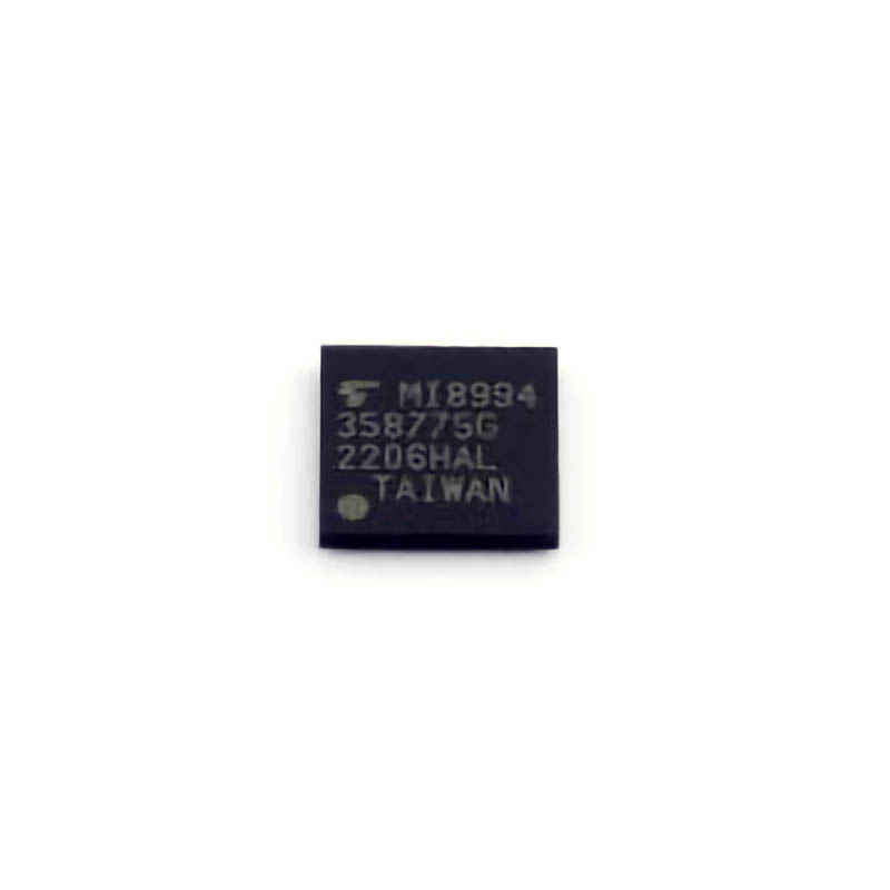
This article offers a detailed exploration of common issues that users may face with the TC358775XBG , a versatile and Power ful video bridge chip. We also provide expert troubleshooting techniques and practical solutions for resolving these issues. Whether you're a developer, an engineer, or an enthusiast, this guide will help you optimize the performance and efficiency of the TC358775XBG.
TC358775XBG, troubleshooting, solutions, video bridge chip, HDMI, display, resolution, I2C, interface issues, technical guide, hardware diagnostics
Identifying and Troubleshooting Common Issues with the TC358775XBG
The TC358775XBG is a sophisticated video bridge chip designed to support high-definition video conversion and interface management. As a part of Toshiba’s lineup, it facilitates HDMI-to-MIPI DSI and other video format conversions in embedded systems. However, like all hardware components, users may occasionally encounter technical issues. This section will focus on common issues associated with the TC358775XBG and how to troubleshoot them effectively.
1. No Video Output or Blank Screen
One of the most common issues users face when working with the TC358775XBG is no video output or a blank screen, despite the chip being properly powered on. There could be several reasons for this problem, and here’s how to troubleshoot it:
a) Incorrect Video Source
The TC358775XBG relies on a correct video input source, such as HDMI. First, ensure that the HDMI source device (e.g., a laptop, Blu-ray player, or game console) is turned on and properly connected to the TC358775XBG input. Verify that the video source is functioning by testing it on another screen.
b) Misconfigured Resolution Settings
If the video source is correct but the screen remains blank, the resolution or format settings might be incorrect. The TC358775XBG supports various video resolutions and display formats, but mismatches between the source and output could result in no image being displayed.
Solution: Double-check the output resolution and format settings on the chip. Make sure that the resolution you have set for the output display matches the capabilities of the connected MIPI DSI panel. For example, try lowering the resolution or testing with a different display panel that supports the same resolution.
c) Signal Integrity Issues
Another possibility is signal integrity problems, such as electrical noise or interference that prevents the proper transmission of video data. This is especially common in environments with many devices or high-speed signals. Poor connections, such as loose cables or dirty connectors, could also contribute to the issue.
Solution: Inspect all connections and cables for any loose or damaged parts. Also, ensure that the power supply is stable and that there are no fluctuations that could cause instability in the signal transmission. Use high-quality cables for both the HDMI and MIPI interfaces.
d) Firmware and Driver Issues
If you’re using the TC358775XBG as part of a custom embedded system, outdated or faulty firmware might be the cause of the issue. Sometimes, the device drivers for the HDMI or MIPI interfaces might not be configured correctly.
Solution: Update the firmware to the latest version and verify that the device drivers for both the HDMI input and MIPI output are correctly installed. Refer to the official documentation and ensure you’re using the correct driver version for your platform.
2. Color Distortion or Pixel Artifacts
Users may sometimes encounter issues with color distortion or pixel artifacts when using the TC358775XBG. These problems can be caused by a variety of factors, including misconfigured settings or hardware-related issues.
a) Incorrect Timing or Data Lane Configuration
In systems that use MIPI DSI for display output, the timing or lane configuration must match the display panel's specifications. If the data lanes or clock rates are incorrectly set, you may see color distortion, horizontal lines, or even a completely garbled display.
Solution: Verify that the MIPI clock frequency and data lane configuration match the specifications of the display panel you're using. Use a logic analyzer or oscilloscope to check the MIPI signals for any discrepancies.
b) Signal Noise or Power Supply Issues
A common cause of pixel artifacts is signal noise, especially if the power supply is not stable or if the signal cables are too long or poorly shielded. Power supply fluctuations can introduce artifacts into the video signal, causing pixels to display incorrect colors.
Solution: Use a high-quality, regulated power supply and ensure that the input signal is stable. In addition, check the integrity of the MIPI and HDMI cables, and use shorter cables where possible to minimize signal degradation.
c) Incompatible Video Format
The TC358775XBG supports multiple video formats, but mismatches between the input video format and the output capabilities of the MIPI display can lead to color distortion.
Solution: Check the video format settings in both the source device (e.g., HDMI input) and the TC358775XBG. Ensure that the color depth and pixel format (e.g., RGB or YCbCr) are compatible with both devices.
3. I2C Communication Problems
The TC358775XBG utilizes the I2C interface for configuration and control. Communication problems can arise if the I2C bus is misconfigured, or if there are physical issues with the wiring or bus itself.
a) Incorrect I2C Address or Configuration
If you’re unable to communicate with the TC358775XBG over I2C, first check whether the correct I2C address is being used. Incorrect addressing is one of the primary reasons for communication failure.
Solution: Verify the I2C address through the datasheet and configuration software. Use an I2C scanner tool to check for the device’s presence on the bus. If necessary, reassign the I2C address or ensure that the pull-up resistors are correctly placed.
b) Noise or Poor Connection on the I2C Bus
I2C communication can be sensitive to electrical noise, especially in high-speed systems. Inadequate grounding, long wire lengths, or poor connections can disrupt communication.
Solution: Use proper grounding and keep the I2C traces as short as possible. Ensure the pull-up resistors on the SDA and SCL lines are of the correct value (typically 4.7kΩ), and check the I2C bus for any signs of noise or interference.
4. Power Supply and Overheating Issues
The TC358775XBG can also experience issues related to power supply instability or excessive heat. Power instability can cause erratic behavior, including loss of video output or complete failure to power on.
a) Power Supply Voltage Fluctuations
Ensure that the power supply is providing a stable voltage to the TC358775XBG. Voltage drops or spikes can cause the chip to malfunction or enter an unstable state.
Solution: Use a regulated power supply and monitor the voltage with a multimeter or oscilloscope. Make sure that the voltage is within the recommended range for the TC358775XBG (typically 1.8V for the core and 3.3V for I/O).
b) Overheating
If the chip becomes too hot, it may shut down or behave unpredictably. Overheating can result from poor thermal design or insufficient cooling in embedded systems.
Solution: Ensure that the TC358775XBG is properly ventilated or that a heat sink is attached if necessary. Monitor the temperature during operation, and consider adding additional cooling if the chip runs hot under heavy load.
Advanced Troubleshooting and Long-Term Solutions for the TC358775XBG
In this second part, we will explore more advanced troubleshooting techniques and strategies to ensure the TC358775XBG operates reliably over the long term. These solutions will help developers and engineers optimize system performance and avoid recurring issues.
5. Advanced Diagnostic Tools and Techniques
For more complex problems, advanced diagnostic tools such as oscilloscopes, logic analyzers, and software debugging tools can be invaluable in identifying the root cause of an issue.
a) Using an Oscilloscope to Analyze Signal Integrity
Signal integrity problems can often be the source of video output issues, such as pixel artifacts or distorted colors. Using an oscilloscope to monitor the HDMI or MIPI signal can provide a detailed view of the problem.
Solution: Probe the HDMI input and MIPI output lines with an oscilloscope to check for signal degradation or noise. Look for irregularities such as signal ringing, overshooting, or undershooting, which can affect the quality of the video signal.
b) Logic Analyzer for I2C Communication
A logic analyzer is particularly useful for debugging I2C communication issues. It allows you to visualize the communication between the TC358775XBG and the controller, helping identify problems with address conflicts, data corruption, or timing errors.
Solution: Connect a logic analyzer to the I2C bus and capture the communication between the TC358775XBG and the microcontroller. Analyze the captured data for timing issues, incorrect commands, or failure to acknowledge signals.
6. Custom Firmware and Software Updates
For those working with embedded systems or custom hardware, software and firmware updates can resolve many issues related to compatibility and functionality. It is crucial to stay up-to-date with the latest firmware provided by Toshiba.
a) Updating Firmware
Firmware updates often include bug fixes, new features, and optimizations for better performance. Always ensure that the TC358775XBG is running the latest firmware version available from Toshiba.
Solution: Visit Toshiba’s official website or your hardware provider’s portal to check for firmware updates. Follow the update instructions carefully, and test the system after updating the firmware to ensure the issue is resolved.
b) Custom Software for Display Control
If you are using the TC358775XBG in a custom application, consider writing your own control software to better manage display settings and video input/output. Custom software gives you more control over the system and can help prevent issues caused by misconfiguration or incompatibilities.
Solution: Develop a custom control application that interacts with the TC358775XBG’s I2C interface to configure the video settings and parameters. Use this software to fine-tune the resolution, color depth, and display orientation to match your hardware specifications.
7. Environmental and System Considerations
Environmental factors and system design can have a significant impact on the performance of the TC358775XBG. For instance, operating the chip in a high-temperature environment or in a system with inadequate grounding can lead to frequent issues.
a) Improved Grounding and Shielding
In embedded systems, proper grounding and shielding can prevent many signal integrity problems, including those that affect video output.
Solution: Ensure that the TC358775XBG is mounted on a properly grounded PCB, and that all signal lines are shielded from electromagnetic interference ( EMI ). Use ground planes on the PCB and implement shielding enclosures around sensitive components.
b) Long-Term Maintenance and Monitoring
Lastly, it’s essential to consider the long-term reliability of the TC358775XBG. Monitoring the chip's performance over time and conducting regular maintenance checks can help catch issues before they become critical.
Solution: Implement system health monitoring software that checks for anomalies such as unusual power consumption or temperature spikes. Periodically inspect connectors and cables to ensure they remain in good condition.
By understanding and addressing these common and advanced troubleshooting techniques, users can maintain the TC358775XBG’s performance and ensure that their systems run smoothly for the long term. With careful attention to power supply, signal integrity, firmware, and environmental factors, you can resolve most problems and get the most out of this versatile video bridge chip.
If you are looking for more information on commonly used Electronic Components Models or about Electronic Components Product Catalog datasheets, compile all purchasing and CAD information into one place.
Partnering with an electronic components supplier sets your team up for success, ensuring the design, production, and procurement processes are quality and error-free.


