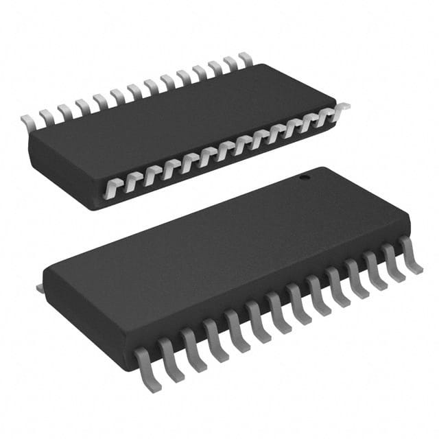
The PIC18F26K22-I/SO is a popular 8-bit microcontroller, widely used in embedded systems. However, like any complex component, users may face several challenges when integrating it into their projects. This article provides a comprehensive troubleshooting guide to help engineers and hobbyists resolve common issues, ensuring smooth operation and optimal performance.
PIC18F26K22, troubleshooting, microcontroller, solutions, embedded systems, firmware, debugging, I/O issues, Communication protocols, Power management
Common Troubleshooting Issues with the PIC18F26K22-I/SO
The PIC18F26K22-I/SO is a versatile microcontroller from Microchip's 18-bit family, offering excellent performance and a range of features, including PWM, ADC, and I2C communication. However, like all embedded systems, issues can arise during development. In this first part of the guide, we’ll cover some of the most common problems users encounter when working with this microcontroller and explore possible solutions.
1. Power Supply Issues
Power-related problems are one of the most common sources of malfunction in embedded systems. If the PIC18F26K22-I/SO is not receiving a stable and sufficient supply of voltage, it will fail to operate as expected.
Symptoms:
The microcontroller does not start or intermittently resets.
Unpredictable behavior of the system.
Possible Causes:
Incorrect Voltage: The PIC18F26K22 operates at 2.0V to 5.5V, with typical applications running at 5V. Ensure that the power supply is within this range and is stable.
Power Supply Fluctuations: Noise or fluctuations in the power supply can cause the microcontroller to behave erratically. Using capacitor s (e.g., 100nF near the power pins) can help filter out noise.
Insufficient Current: If the peripheral devices or sensors connected to the microcontroller draw more current than the power supply can provide, it can cause resets or erratic behavior.
Solution:
Verify the voltage level using a multimeter or oscilloscope to check for stability and correct voltage.
Use decoupling capacitors near the power pins to smooth out any voltage spikes or dips.
Ensure that the power supply can provide enough current for the entire circuit, including sensors and other connected peripherals.
2. Incorrect Configuration of I/O Pins
The PIC18F26K22-I/SO microcontroller has a range of general-purpose I/O (GPIO) pins that can be configured for various functions such as analog inputs, digital I/O, or PWM output. Misconfiguration of these pins can lead to non-functional circuits or erroneous behavior.
Symptoms:
Inconsistent input readings.
Outputs not responding as expected.
Possible Causes:
Wrong Pin Mode: GPIO pins need to be configured as input or output, and sometimes as analog or digital. Misconfiguration in the firmware can cause a pin to behave unpredictably.
Pin Multiplexing: The PIC18F26K22 allows for multiplexed functions on many pins. Ensure that each pin is properly configured in the firmware for its intended function.
Solution:
Use the TRIS registers to set the direction of each I/O pin (input or output).
Use the ADCON1 register to configure the pins for digital or analog operation.
Double-check the pin assignments in the datasheet for any conflicting functions.
3. Programming and Debugging Errors
Programming the PIC18F26K22-I/SO often involves debugging the firmware to resolve logical errors. Sometimes, issues arise due to incorrect programming or debugging setups.
Symptoms:
Code does not execute as expected.
The device does not respond to input.
Possible Causes:
Incorrect Fuses and Configuration Bits: The PIC18F26K22 has various fuse settings that control key features like the clock source, watchdog timer, and brown-out detection. If these fuses are not correctly set, the microcontroller may not behave as expected.
Programming Interface Issues: Inaccurate or incomplete programming of the microcontroller can also lead to problems. Ensure that you are using the correct programmer and that it is properly connected.
Solution:
Review the configuration bits in your code to ensure that they match the desired settings for your application. This includes clock settings, watchdog timers, and brown-out detection.
Use a known good programmer (such as a PICkit or ICD) and ensure that it is properly connected to the target board. If necessary, try reprogramming the microcontroller or performing a "blank check" to verify that the program memory is intact.
4. Communication Protocol Failures
The PIC18F26K22-I/SO supports several communication protocols such as SPI, I2C, and UART. Issues with these protocols are commonly encountered during development.
Symptoms:
Failed data transmission or reception.
Devices not responding to communication.
Possible Causes:
Incorrect Baud Rate: When using UART, I2C, or SPI, an incorrect baud rate or clock speed mismatch can cause communication failures.
Bus Contention: If multiple devices are sharing the same bus (e.g., I2C or SPI), conflicting signals can disrupt communication.
Improper Pull-up Resistors : For I2C and certain SPI configurations, improper use of pull-up resistors can cause communication problems.
Solution:
Double-check the baud rate and clock settings for communication protocols. Ensure that they match the specifications of the connected devices.
If using I2C, ensure that the SDA and SCL lines are connected with appropriate pull-up resistors (typically 4.7kΩ).
For SPI, check the clock polarity, phase, and speed to match the slave device settings.
Use an oscilloscope to verify the integrity of the communication signals.
Advanced Troubleshooting and Best Practices for PIC18F26K22-I/SO
In this second part, we’ll dive into more advanced troubleshooting strategies and best practices to help you maximize the performance of your PIC18F26K22-I/SO microcontroller.
1. Watchdog Timer (WDT) Issues
The PIC18F26K22 includes a watchdog timer (WDT) that can be used to reset the microcontroller if it gets stuck in an infinite loop or experiences other software faults. While this feature can improve system reliability, it can also cause unintended resets if not handled correctly.
Symptoms:
The microcontroller resets unexpectedly.
The system enters a reset loop.
Possible Causes:
Unintended WDT Trigger: If the software does not properly clear the WDT within the defined timeout period, it will trigger a reset.
Improper WDT Configuration: The WDT needs to be enabled and configured correctly to avoid false triggers.
Solution:
Ensure that the WDT is cleared at appropriate intervals in your code using the ClrWdt instruction.
If the WDT is not needed, consider disabling it by setting the appropriate configuration bits.
Review the WDT timeout period and adjust it according to the application's needs.
2. Reset Circuit Design
A well-designed reset circuit is crucial for reliable operation. PIC18F26K22 requires a clean reset signal to ensure that it starts up properly.
Symptoms:
The microcontroller does not boot up consistently.
Peripheral devices do not initialize correctly.
Possible Causes:
Improper Reset Pulse Width: The reset signal must meet the required minimum pulse width specified in the datasheet. A too-short pulse may fail to trigger a proper reset.
Noisy Reset Line: A noisy or floating reset line can cause inconsistent behavior, especially during power-up.
Solution:
Use a dedicated reset IC (e.g., an external supervisor) to ensure a clean reset signal.
Ensure that the reset pulse width meets the minimum requirement and that the signal is stable and noise-free.
3. Code Optimization for Reliability
Code optimization is not just about improving speed; it's also about making your system more reliable and easier to debug. Inefficient or poorly structured code can lead to obscure bugs and unexpected behavior.
Symptoms:
Unexpected behavior under specific conditions.
Excessive power consumption or slow performance.
Possible Causes:
Inefficient Interrupt Handling: Interrupt routines should be as short and efficient as possible. Long or blocking interrupt handlers can affect the overall system responsiveness.
Overuse of Global Variables: Excessive use of global variables can make debugging more challenging and lead to difficult-to-track bugs.
Solution:
Keep interrupt service routines (ISRs) as brief as possible, and avoid using delay functions within them.
Use local variables within functions instead of global variables to reduce complexity.
Optimize the code to minimize the use of unnecessary delays and polling.
4. Use of Debugging Tools
Effective debugging tools can save time and help pinpoint issues more quickly. Tools like MPLAB X IDE, MPLAB ICD, and logic analyzers are invaluable for troubleshooting.
Symptoms:
Inability to identify the root cause of issues.
Long development cycles due to trial-and-error debugging.
Possible Causes:
Lack of Debugging Tools: Without proper debugging tools, troubleshooting can be slow and inefficient.
Improper Use of Debugging Tools: Misconfiguring your debugger can lead to inaccurate or incomplete information.
Solution:
Use the MPLAB X IDE for in-depth code analysis and debugging. Take advantage of breakpoints, step-through execution, and peripheral simulation.
If using an external debugger, ensure that it is compatible with your setup and properly configured.
Utilize a logic analyzer or oscilloscope to monitor communication signals in real-time.
By following these troubleshooting steps and best practices, you can address most of the common issues encountered when working with the PIC18F26K22-I/SO microcontroller. By ensuring correct power, I/O configuration, programming, and communication setup, you’ll be able to maximize the performance and reliability of your embedded systems.
If you are looking for more information on commonly used Electronic Components Models or about Electronic Components Product Catalog datasheets, compile all purchasing and CAD information into one place.
Partnering with an electronic components supplier sets your team up for success, ensuring the design, production, and procurement processes are quality and error-free.


