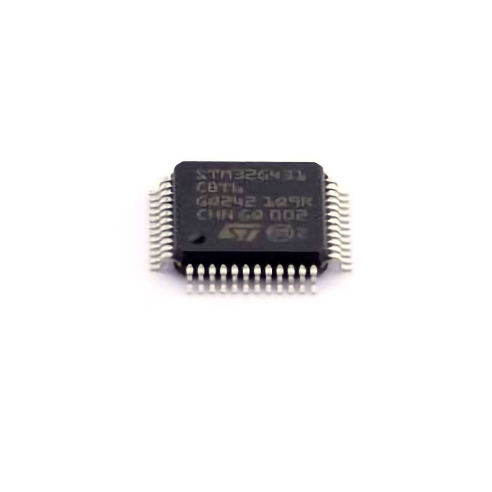
This article explores the application and coding aspects of the STM32G431CBT6 microcontroller for high-performance motor control. It provides detailed insights into motor control applications, the integration of STM32G431CBT6 with motor control algorithms, and practical examples using this powerful microcontroller. The content covers both theoretical and practical aspects, making it ideal for engineers, developers, and enthusiasts in the field of motor control systems.
STM32G431CBT6, high-performance motor control, motor control systems, STM32G431, motor control algorithms, microcontroller applications, embedded systems, BLDC motor control, FOC algorithm, PWM generation, STM32CubeIDE, STM32CubeMX, motor driver integration, sensorless control
Introduction to STM32G431CBT6 for High-Performance Motor Control
The STM32G431CBT6 microcontroller is part of the STM32G4 series from STMicroelectronics, designed specifically to address the growing need for high-performance embedded systems. With a strong focus on efficiency, flexibility, and advanced control features, the STM32G431CBT6 is a prime choice for applications in motor control, especially where precision, responsiveness, and low power consumption are paramount.
Motor control has always been a challenging area of embedded systems due to the complexity involved in driving motors with high efficiency, smoothness, and precision. The STM32G431CBT6 comes with a range of built-in features that simplify the design and optimization of motor control systems. These features include advanced timers, high-speed ADCs, DACs, and a range of Communication interface s that allow seamless integration with motor drivers, sensors, and other components.
Why STM32G431CBT6?
The STM32G431CBT6 is based on an ARM Cortex-M4 core with a Floating Point Unit (FPU) operating at 170 MHz. This combination of speed and computational power makes it well-suited for high-performance applications like motor control. The microcontroller also offers a variety of peripherals that are highly useful for controlling motors, such as advanced timers for precise PWM signal generation, high-resolution ADCs for sensor feedback, and a wide range of communication options like SPI, I2C, UART, and CAN for system integration.
Key Features for Motor Control
Advanced Timer System:
The STM32G431CBT6 features advanced timers with features like dead-time insertion, complementary PWM outputs, and synchronization. These timers are vital for controlling motor speed and torque in applications such as Brushless DC (BLDC) motors, Stepper motors, and Permanent Magnet Synchronous Motors (PMSM).
High-Speed ADCs (Analog-to-Digital Converters ):
Motor control systems often rely on feedback from sensors such as encoder s, Hall effect sensors, or current sensors. The STM32G431CBT6 has high-speed, 12-bit ADCs with up to 3.6 Msps, enabling fast and accurate data acquisition. This ensures real-time motor performance monitoring and closed-loop control.
PWM Generation:
Pulse Width Modulation (PWM) is a critical technique in motor control for regulating voltage and current to the motor windings. The STM32G431CBT6 includes timers capable of generating high-resolution PWM signals, which are essential for smooth motor operation and minimizing electromagnetic interference ( EMI ).
Communication Interfaces:
Communication interfaces like SPI and CAN allow easy integration with motor drivers and other peripheral devices. This is especially important in industrial motor control systems that require communication with remote sensors, motor controllers, or supervisory systems.
Floating-Point Unit (FPU):
The presence of an FPU accelerates the computation of motor control algorithms such as Field-Oriented Control (FOC), which involves complex mathematical operations. The FPU ensures that these operations are performed quickly, making real-time control feasible.
Motor Control Algorithms
The STM32G431CBT6 is particularly well-suited for implementing advanced motor control algorithms. Among these, Field-Oriented Control (FOC) is the most commonly used technique for high-performance motor control. FOC is known for its ability to deliver precise control over the motor’s speed and torque by decoupling the control of the motor’s magnetic field and armature.
Field-Oriented Control operates in a two-phase rotating coordinate system where the d-axis represents the direct axis (aligned with the magnetic field) and the q-axis represents the quadrature axis. By controlling the current in these two axes independently, FOC ensures that the motor operates at optimal efficiency and torque for any given speed.
The STM32G431CBT6, with its powerful processing capabilities and high-speed peripherals, makes the implementation of FOC algorithms efficient and effective. These algorithms involve real-time computations for motor current, voltage, and speed, and are optimized through the use of hardware accelerators, floating-point operations, and PWM generation.
Example Use Case: BLDC Motor Control
A Brushless DC (BLDC) motor is commonly used in applications requiring high efficiency, such as in electric vehicles, drones, and robotics. To control a BLDC motor, the STM32G431CBT6 can interface with Hall sensors or a sensorless control algorithm to detect the rotor position. Based on this position, the microcontroller generates the appropriate PWM signals to the motor driver, controlling the motor’s speed and torque.
The implementation of the Field-Oriented Control (FOC) algorithm on the STM32G431CBT6 ensures smooth commutation of the BLDC motor, leading to efficient operation and reduced motor heating. Through the integration of current sensors, the microcontroller continuously adjusts the motor drive to maintain optimal performance.
In the next section, we will dive deeper into the practical integration of STM32G431CBT6 in motor control systems with specific code examples and integration strategies.
Practical Code Examples and Integration Strategies for Motor Control with STM32G431CBT6
In this section, we will explore the practical aspects of integrating the STM32G431CBT6 into high-performance motor control systems. By walking through code examples and system design considerations, this part aims to provide a hands-on understanding of how to leverage the capabilities of the STM32G431CBT6 to implement motor control algorithms.
Setting Up the Development Environment
Before diving into the code, it's crucial to set up the development environment. The STM32G431CBT6 is compatible with STM32CubeIDE, an integrated development environment that combines code editing, compilation, and debugging tools for STM32 microcontrollers.
Install STM32CubeIDE: Download and install STM32CubeIDE from the STMicroelectronics website.
Create a New Project: Launch STM32CubeIDE and create a new STM32 project. Select the STM32G431CBT6 microcontroller and initialize the necessary peripherals like timers, ADCs, PWM channels, and communication interfaces.
Use STM32CubeMX: STM32CubeMX can be used to configure the microcontroller’s pins and peripherals. It simplifies the process of generating initialization code for the MCU.
Code Example 1: Generating PWM for Motor Control
A key part of motor control involves generating PWM signals for controlling the motor’s speed and direction. Below is a basic example of how to configure a timer to generate PWM signals using STM32CubeIDE.
#include "main.h"
TIM_HandleTypeDef htim1;
void HAL_TIM_PWM_MspInit(TIM_HandleTypeDef* htim_pwm)
{
GPIO_InitTypeDef GPIO_InitStruct = {0};
if(htim_pwm->Instance == TIM1)
{
__HAL_RCC_TIM1_CLK_ENABLE();
__HAL_RCC_GPIOA_CLK_ENABLE();
GPIO_InitStruct.Pin = GPIO_PIN_8; // PWM output pin
GPIO_InitStruct.Mode = GPIO_MODE_AF_PP;
GPIO_InitStruct.Pull = GPIO_NOPULL;
GPIO_InitStruct.Speed = GPIO_SPEED_FREQ_HIGH;
HAL_GPIO_Init(GPIOA, &GPIO_InitStruct);
}
}
void PWM_Init(void)
{
__HAL_RCC_TIM1_CLK_ENABLE();
htim1.Instance = TIM1;
htim1.Init.Prescaler = 0;
htim1.Init.CounterMode = TIM_COUNTERMODE_UP;
htim1.Init.Period = 1000 - 1; // PWM frequency (1kHz)
htim1.Init. Clock Division = TIM_CLOCKDIVISION_DIV1;
HAL_TIM_PWM_Init(&htim1);
// PWM Channel configuration
TIM_OC_InitTypeDef sConfigOC = {0};
sConfigOC.OCMode = TIM_OCMODE_PWM1;
sConfigOC.Pulse = 500; // 50% Duty Cycle
sConfigOC.OCPolarity = TIM_OCPOLARITY_HIGH;
HAL_TIM_PWM_ConfigChannel(&htim1, &sConfigOC, TIM_CHANNEL_1);
HAL_TIM_PWM_Start(&htim1, TIM_CHANNEL_1);
}
int main(void)
{
HAL_Init();
SystemClock_Config();
// Initialize PWM
PWM_Init();
while (1)
{
// Adjust PWM duty cycle for motor speed control
__HAL_TIM_SET_COMPARE(&htim1, TIM_CHANNEL_1, 750); // 75% Duty Cycle
HAL_Delay(1000);
__HAL_TIM_SET_COMPARE(&htim1, TIM_CHANNEL_1, 250); // 25% Duty Cycle
HAL_Delay(1000);
}
}
In this code example, the PWM signal is generated using Timer 1 (TIM1) on GPIO pin PA8. The HAL_TIM_PWM_Init function configures the timer, and the HAL_TIM_PWM_ConfigChannel function sets up the PWM signal. The duty cycle is adjusted dynamically in the main loop.
Code Example 2: Implementing Field-Oriented Control (FOC)
Implementing Field-Oriented Control (FOC) requires precise calculation of motor currents and rotor position. For simplicity, we’ll outline the basic structure of an FOC implementation, though in practice, this involves more complex algorithms and hardware.
#include "math.h"
#include "main.h"
#define PI 3.14159265
// Variables for motor control
float Id, Iq; // D and Q axis current components
float Vd, Vq; // D and Q axis voltage components
float theta; // Rotor angle
float speed; // Rotor speed
// Simplified FOC algorithm function
void FOC_Algorithm(void)
{
// Get the rotor position (e.g., from an encoder or sensorless algorithm)
theta = getRotorAngle();
// Calculate Id and Iq currents using the reference frame transformation
Id = getCurrentD();
Iq = getCurrentQ();
// Calculate voltage commands for d and q axes
Vd = Kp * Id + Ki * speed; // Control law for d-axis
Vq = Kp * Iq + Ki * speed; // Control law for q-axis
// Apply voltage to the motor (via PWM)
setMotorVoltage(Vd, Vq);
}
int main(void)
{
HAL_Init();
SystemClock_Config();
// Initialize motor control
initMotorControl();
while (1)
{
FOC_Algorithm(); // Call the FOC algorithm to control motor speed and torque
}
}
This example illustrates a simplified approach to implementing the FOC algorithm, where Vd and Vq are the calculated voltage components in the direct and quadrature axes. The getCurrentD() and getCurrentQ() functions simulate the process of obtaining motor current feedback, and the setMotorVoltage() function would use PWM to adjust the motor voltage.
Conclusion
The STM32G431CBT6 microcontroller offers a powerful platform for implementing high-performance motor control algorithms such as FOC. By combining its fast processing power, high-resolution peripherals, and extensive development support, engineers can efficiently design and deploy motor control systems with high precision and reliability.
If you are looking for more information on commonly used Electronic Components Models or about Electronic Components Product Catalog datasheets, compile all purchasing and CAD information into one place.


