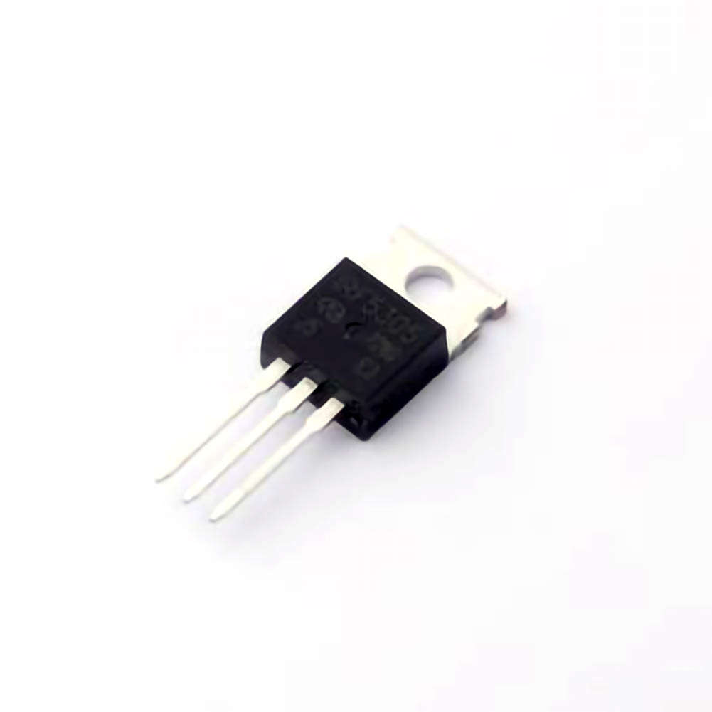
This article explores the role and significance of the IRF5305 P-channel MOSFET in inverter circuits. It provides insights into the key applications, advantages, and optimization strategies for achieving efficient inverter operation. It also discusses how this component enhances pe RF ormance in various inverter-based Power electronics systems.
IRF530 5, P-channel MOSFET, inverter, power electronics, optimization, efficiency, switching, power conversion, circuit design, electronic components.
The Importance of the IRF5305 P-Channel MOSFET in Inverter Circuits
Inverter circuits are crucial components in modern power systems, facilitating the conversion of DC (direct current) to AC (alternating current). In various applications—from renewable energy systems like solar panels to uninterruptible power supplies (UPS)—the performance and efficiency of Inverters are paramount. At the heart of these power conversion systems lie critical components such as transistor s, capacitor s, and inductors. Among these, the IRF5305 P-channel MOSFET stands out as an excellent choice for optimizing inverter performance, thanks to its exceptional switching characteristics and robust power-handling capabilities.
The Role of P-Channel MOSFETs in Inverter Circuits
MOSFETs (Metal-Oxide-Semiconductor Field-Effect Transistors) are integral to the operation of inverter circuits. These transistors are used to control the flow of electrical current in the circuit. The P-channel MOSFET is particularly important for the high-side switching in inverters. High-side switching refers to turning the positive terminal of the DC power supply on and off in relation to the load, and it is crucial for the efficient conversion of power.
The IRF5305 is a high-performance P-channel MOSFET designed to work in high-voltage applications, making it ideal for use in inverter circuits that require switching of higher currents and voltages. With a voltage rating of 55V and a continuous drain current of 18A, the IRF5305 is capable of delivering stable and efficient operation in power conversion systems. Its low Rds(on) (on-resistance) ensures minimal power loss during operation, which is essential for enhancing the overall efficiency of the inverter.
Key Features of the IRF5305
Several key characteristics make the IRF5305 an excellent choice for inverter circuits:
High Voltage Rating (55V): The IRF5305 can handle voltages up to 55V, making it suitable for most inverter applications, including those dealing with DC voltages up to 48V, which is typical in renewable energy systems or battery-operated devices.
Low Rds(on): The on-resistance of the IRF5305 is low, ensuring that the power losses in the device are minimal. This translates to better thermal efficiency and less energy wasted as heat.
High Switching Speed: The MOSFET’s fast switching capabilities enable quick response times, a crucial factor in high-frequency inverter circuits. This leads to higher efficiency in power conversion and smoother operation of the inverter.
Thermal Stability: With excellent thermal Management characteristics, the IRF5305 can dissipate heat effectively, ensuring the longevity of both the MOSFET and the inverter system.
These features make the IRF5305 highly reliable in inverter circuits, providing efficient switching and minimizing energy losses during power conversion.
Inverter Applications of the IRF5305
The IRF5305’s performance characteristics are well-suited for a variety of inverter applications, from small-scale consumer electronics to larger industrial systems. Some of the most prominent uses include:
Solar Inverters: In solar energy systems, DC power generated by photovoltaic panels needs to be converted to AC for use in homes or businesses. The IRF5305 P-channel MOSFET is perfect for switching in the high-side configuration, which is essential for the smooth operation of solar inverters.
Uninterruptible Power Supplies (UPS): UPS systems rely on efficient inverters to maintain power during outages. The IRF5305 can efficiently switch between the battery and AC power sources, ensuring seamless power delivery.
DC-AC Power Conversion: For systems that need to convert DC battery or renewable energy output into AC for various applications (like motor drives, lighting, or home appliances), the IRF5305 provides a stable and efficient solution.
Motor Drives and Electric Vehicles (EVs): In motor control circuits for electric vehicles, the IRF5305 offers reliable high-side switching that helps in controlling the motors effectively while maintaining high efficiency.
Optimizing the IRF5305 P-Channel MOSFET for Maximum Efficiency in Inverter Circuits
While the IRF5305 offers impressive characteristics straight out of the box, achieving optimal performance in inverter circuits requires thoughtful optimization of the overall system design. Several techniques can be employed to maximize the MOSFET’s efficiency and enhance the inverter’s performance.
Gate Drive Optimization for Faster Switching
One of the primary factors affecting the efficiency of MOSFETs in inverter circuits is the speed at which they switch. The IRF5305, like most MOSFETs, requires a proper gate drive signal to ensure fast switching. Slow gate switching can lead to prolonged periods of high power dissipation, especially during the transition between on and off states.
To optimize the gate drive, designers often use dedicated MOSFET driver ICs that can supply the required voltage and current to the gate of the IRF5305 quickly and efficiently. This ensures that the MOSFET switches on and off in a timely manner, reducing switching losses. It’s crucial to select a gate driver with high current output and fast rise/fall times to ensure minimal switching delay.
Thermal Management for Improved Reliability
Thermal performance is critical when dealing with high-power devices like the IRF5305. The MOSFET generates heat during operation, particularly when switching large currents. Effective thermal management is essential to maintain the longevity and reliability of both the MOSFET and the inverter system.
Using heat sinks, thermal pads, and improving airflow within the inverter enclosure are common ways to manage heat dissipation. Additionally, careful PCB design—such as using thick copper traces for current paths and minimizing the distance between components—can help reduce heat buildup in the MOSFET.
Another thermal consideration is the ambient temperature in which the inverter operates. For systems operating in environments with high temperatures, it may be necessary to select MOSFETs with higher current ratings or incorporate additional cooling mechanisms, such as fans or liquid cooling.
Enhancing Efficiency with Proper Layout Design
Layout design in power circuits plays a crucial role in reducing losses and improving the overall efficiency of the inverter. When using the IRF5305 P-channel MOSFET, it is important to minimize parasitic inductance and resistance in the circuit layout. For example, keeping the gate and drain traces as short and direct as possible reduces the likelihood of voltage spikes that can lead to unnecessary losses.
The PCB layout should ensure that the MOSFET's source and drain terminals are properly connected to minimize the impact of parasitic elements. Additionally, it’s recommended to use low-resistance, high-conductivity materials for power paths to minimize power dissipation.
Voltage and Current Protection
Inverter circuits often deal with high voltages and currents, which can potentially damage components if not properly protected. For the IRF5305 to operate efficiently and safely, designers need to implement over-voltage and over-current protection mechanisms. These can include:
Snubber circuits: To protect the MOSFET from voltage spikes caused by switching transients.
Current sensing: To monitor the current flow through the MOSFET and prevent overcurrent situations.
Clamping diodes: To safeguard the MOSFET from voltage spikes that could exceed its voltage rating.
By using these protection techniques, the system can operate at higher efficiency levels without risking component failure.
Switching Frequency Considerations
The switching frequency of the inverter is another important factor in optimizing the IRF5305 P-channel MOSFET. While higher switching frequencies can lead to smaller passive components (inductors and capacitors), they also introduce higher switching losses due to the MOSFET's intrinsic capacitance. Therefore, choosing an optimal switching frequency is essential for balancing efficiency with size.
In general, low to medium switching frequencies (e.g., 20-50 kHz) work best for systems using the IRF5305. Going beyond this range may result in diminished returns in terms of efficiency, as the switching losses become more significant.
Conclusion
The IRF5305 P-channel MOSFET is a powerful component in the design of high-performance inverter circuits. By capitalizing on its low Rds(on), high voltage rating, and fast switching capabilities, designers can create efficient and reliable inverter systems for a variety of applications, including renewable energy, motor control, and uninterruptible power supplies.
Optimization strategies such as improving gate drive circuits, managing thermal dissipation, optimizing PCB layout, and implementing proper protection mechanisms are key to maximizing the performance of the IRF5305 in inverter circuits. As power conversion demands continue to grow in industries ranging from consumer electronics to electric vehicles, the role of high-quality components like the IRF5305 will remain central to achieving efficient, reliable, and sustainable energy solutions.
If you are looking for more information on commonly used Electronic Components Models or about Electronic Components Product Catalog datasheets, compile all purchasing and CAD information into one place.


