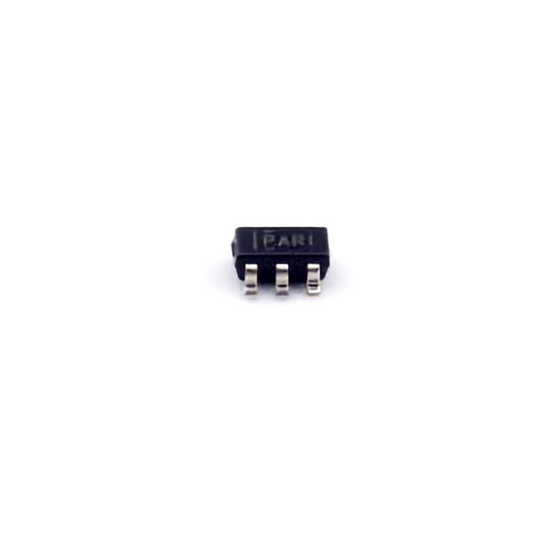
Understanding the TPS3823-33DBVR and Its Common Issues
The TPS3823-33DBVR is a highly reliable voltage supervisor IC from Texas Instruments. It is widely used in various applications where precise voltage monitoring is required, including Power supply systems, embedded systems, and consumer electronics. The chip monitors the power supply voltage and generates an output signal that can be used to reset or control other parts of the system if the supply voltage falls outside the specified limits. This is particularly critical in preventing malfunctions in devices where power stability is essential.
Before diving into troubleshooting, it’s important to understand the key functions and features of the TPS3823-33DBVR:
Key Features:
Voltage Monitoring: It monitors the supply voltage and outputs a signal to indicate whether the voltage is within the desired range.
Reset Output: The chip features an active-low reset output that gets triggered if the supply voltage is too high or too low.
Manual Reset Input: The device includes a manual reset pin for external control, allowing engineers to manually initiate a reset when necessary.
Wide Supply Voltage Range: The TPS3823-33DBVR operates with a broad supply range of 0.8V to 6V.
Low Power Consumption: The IC is designed for minimal power consumption, making it ideal for battery-powered devices.
Understanding these basic features can help when diagnosing potential issues, as it provides insight into how the chip should behave under normal operating conditions. If your TPS3823-33DBVR isn’t functioning as expected, it could be due to a number of factors, such as improper configuration, faulty connections, or external interference. Below are some of the most common issues engineers face when using this IC.
1. Reset Behavior Not Triggered Properly
One of the most common issues with the TPS3823-33DBVR is that the reset output doesn’t behave as expected. This can manifest as a reset not being triggered when the supply voltage goes outside the set threshold or not being cleared when the voltage returns to normal levels.
Potential Causes:
Incorrect Threshold Voltage: Ensure that the external resistor divider, if used, is configured correctly to set the desired voltage threshold. A misconfigured divider will result in inaccurate voltage monitoring.
Poor Power Supply Quality: If the input power supply is noisy or fluctuating, it can cause the supervisor IC to incorrectly detect voltage drops or surges, leading to erratic reset behavior.
Inadequate Decoupling capacitor s: Insufficient or improperly placed capacitors can cause supply voltage fluctuations, triggering false resets.
Solution:
Double-check the resistor divider values and make sure they are within the recommended range as specified in the datasheet. Use an oscilloscope to verify the power supply voltage and look for any unwanted fluctuations.
Add proper decoupling capacitors (typically 0.1 µF and 10 µF) near the IC to ensure stable voltage input and to filter out noise.
Verify that the external manual reset pin (if used) is correctly driven. A floating manual reset pin could cause unintended resets.
2. Inconsistent Reset Pulse Duration
Another issue that users sometimes encounter with the TPS3823-33DBVR is an inconsistent reset pulse duration. The IC is designed to generate a reset signal for a fixed duration once the supply voltage is out of tolerance and then release it once the voltage stabilizes.
Potential Causes:
Incorrect Capacitor on Reset Pin: The reset output pulse duration is influenced by the capacitor connected to the reset pin. If the capacitor value is incorrect, the reset pulse duration may be too short or too long.
Voltage Drop on Power Rails: A sudden drop in voltage (due to a load transient, for example) can cause the supervisor to generate a longer reset pulse than expected.
Solution:
Ensure that the capacitor on the reset pin is the correct value (as recommended in the datasheet). If needed, adjust the capacitor to match the reset pulse duration that suits your application.
If voltage dips are causing the issue, consider improving the power supply design to better handle load transients. Adding an additional bulk capacitor may help in smoothing out voltage dips.
3. Failure to Trigger Manual Reset
The TPS3823-33DBVR allows external components to manually trigger a reset via the manual reset pin. However, some users report that pressing the reset button does not trigger the desired reset response.
Potential Causes:
Floating Manual Reset Pin: If the manual reset pin is not properly connected or is floating, the supervisor will not be able to detect the reset signal.
Improper Pull-up or Pull-down Resistor: If a pull-up or pull-down resistor is not properly configured on the manual reset pin, it may not correctly register a reset pulse when triggered.
Solution:
Check the manual reset pin’s connection. Ensure it is properly connected to the reset button and that the signal is being correctly transmitted to the supervisor IC.
Use a pull-up or pull-down resistor (as recommended in the datasheet) on the manual reset pin to ensure the pin is in the correct state when not actively driven.
Advanced Troubleshooting and Practical Solutions
Once you've identified the symptoms of malfunction, it's time to dive deeper into the troubleshooting process and apply some advanced solutions. This section explores additional methods for addressing and solving more complex issues that might arise with the TPS3823-33DBVR.
4. Reset Triggered Prematurely or Too Late
In some cases, users may observe that the reset is triggered either too soon or too late when voltage thresholds are crossed. This can cause significant issues, particularly in systems requiring precise timing and synchronization.
Potential Causes:
Incorrect Threshold Configuration: The threshold voltage might be set too low or too high, leading to premature resets or failure to detect actual voltage drops.
Temperature Variations: The TPS3823-33DBVR’s threshold voltage may shift slightly with temperature changes. This can lead to timing issues in more sensitive applications.
Solution:
Ensure that the voltage threshold is configured correctly, using the recommended resistor values and following the datasheet guidelines closely.
Consider using a temperature-compensated resistor for the voltage divider to minimize temperature-induced shifts in threshold voltage.
Implement additional filtering on the voltage input to smooth out sudden fluctuations that may cause false triggers.
5. Interference and Noise Issues
Electromagnetic interference ( EMI ) or other sources of noise can cause improper functioning of the TPS3823-33DBVR, particularly when the IC is located near high-speed digital circuits or power switching components.
Potential Causes:
Proximity to High-Frequency Signals: The supervisor IC may pick up noise from nearby high-speed logic or power switching devices.
Inadequate Grounding and Shielding: Poor grounding or lack of shielding can exacerbate noise-related issues.
Solution:
Use proper PCB layout techniques to minimize noise pickup. Keep the supervisor IC as far away as possible from noisy power and digital signal lines.
Ground planes and proper decoupling are essential for ensuring a clean power supply input to the TPS3823-33DBVR. Consider placing the decoupling capacitors as close to the IC as possible.
Shielding sensitive areas of the PCB with copper planes or external shields can help reduce EMI and noise interference.
6. Improper Soldering or PCB Layout
A common but often overlooked issue in circuit designs is improper soldering or PCB layout errors, which can cause intermittent issues with the TPS3823-33DBVR’s performance.
Potential Causes:
Cold Solder Joints: Cold solder joints or poor connections can lead to unreliable operation of the reset output.
Incorrect Pin Connections: Misconnections of pins or incorrect routing on the PCB can prevent the supervisor from operating correctly.
Solution:
Inspect all solder joints carefully and use a magnifying glass or microscope to check for cold solder joints or shorts between adjacent pins.
Review the PCB layout to ensure that the power and reset pins are connected correctly according to the datasheet’s recommendations. Consider running design rule checks (DRC) to verify that there are no unintentional shorts or misrouted signals.
In conclusion, troubleshooting the TPS3823-33DBVR involves understanding the key features of the IC, identifying common issues, and using a systematic approach to address these problems. By following the solutions outlined in this guide, engineers can improve the reliability and functionality of their designs, ensuring that the voltage supervisor operates as intended.
Partnering with an electronic components supplier sets your team up for success, ensuring the design, production, and procurement processes are quality and error-free.


