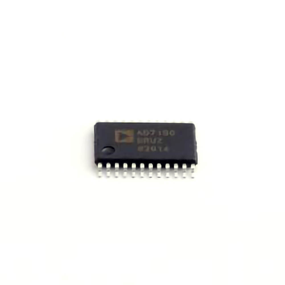
Understanding the AD7190BRUZ and Common Issues
The AD7190BRUZ is a high-precision, low-noise analog-to-digital converter (ADC) designed by Analog Devices. It is often chosen for applications in industrial measurement systems, medical devices, process control, and scientific instrumentation due to its ability to provide accurate and reliable data conversions. However, achieving consistent performance from this ADC requires proper design, calibration, and troubleshooting practices. This article will explore common problems users face with the AD7190BRUZ and how to address them effectively.
1. Power Supply and Grounding Issues
One of the most frequent problems encountered when working with the AD7190BRUZ is related to power supply noise or insufficient grounding. The ADC's performance is highly sensitive to power fluctuations and ground loops. Any instability in the power supply can introduce errors in the ADC output, leading to inaccurate measurements.
Solution:
Stable Power Supply: Ensure the AD7190BRUZ is powered by a stable and noise-free power supply. Utilize low-dropout regulators (LDO) to minimize voltage noise and ripple.
Proper Grounding: Ensure that all ground connections are solid and that there is a single-point ground connection for the ADC. Ground loops can introduce noise into the system, leading to measurement errors.
Decoupling capacitor s: Place decoupling Capacitors close to the power pins of the ADC to filter high-frequency noise. Use capacitors with low equivalent series resistance (ESR) to improve noise suppression.
2. Incorrect Reference Voltage
The AD7190BRUZ uses an external reference voltage (V_ref) to define the input signal range. If this reference voltage is not correctly chosen or suffers from noise, the ADC will produce erroneous conversions. This is one of the most common sources of measurement error.
Solution:
Stable Reference Voltage: Use a precision voltage reference with low noise characteristics for V_ref. A high-quality reference ensures that the ADC's output is directly proportional to the input signal.
Reference Pin Capacitors: Add capacitors between the reference pin and ground to filter high-frequency noise and improve signal stability.
Vref Range: Ensure that the Vref is within the recommended operating range of the ADC. If the reference voltage is too high or too low, the ADC will not function optimally.
3. Input Signal Conditioning Problems
Before the AD7190BRUZ can convert an analog signal into a digital value, the input signal must be properly conditioned. Poor signal conditioning can lead to distortion or inaccuracies in the measurements. Issues such as improper filtering, amplifier gain errors, and impedance mismatch can significantly affect performance.
Solution:
Use Precision Amplifiers : The input signal should be buffered with low-noise, precision operational amplifiers. Ensure that the op-amp is chosen to match the input range and noise requirements of the ADC.
Proper Filtering: Implement anti-aliasing filters to remove high-frequency noise and prevent aliasing. Low-pass filters can help to attenuate unwanted signals and ensure the ADC only converts the desired frequency components.
Impedance Matching: Ensure that the input impedance is properly matched to the ADC's input. A mismatch can result in inaccurate conversions, especially when dealing with high-impedance sources.
4. Timing and Sampling Rate Issues
The AD7190BRUZ supports different sampling rates, and the timing of the sampling process is critical for accurate data acquisition. If the sampling rate is set too high or too low, or if the timing of the input signals is not synchronized with the ADC’s sample Clock , the result can be corrupted or inaccurate data.
Solution:
Sampling Rate Configuration: Carefully set the sampling rate according to the application's requirements. For precise measurements, use the appropriate conversion rate and ensure that the timing of the input signal is in sync with the ADC's sampling process.
Clock Sources: Use a low-jitter clock source to minimize timing errors. Any instability in the clock signal can lead to sampling errors and compromised data accuracy.
Check the Timing Diagram: Consult the datasheet's timing diagram to ensure proper synchronization between the input signal and the ADC’s internal sampling clock.
Advanced Troubleshooting Techniques and Solutions
Now that we have discussed the common problems that users encounter with the AD7190BRUZ, let's explore more advanced troubleshooting techniques and solutions to ensure reliable operation of the device.
5. Temperature Sensitivity
Like many precision components, the AD7190BRUZ is sensitive to temperature changes. Environmental factors such as temperature fluctuations can introduce drift in the ADC’s output, leading to measurement inaccuracies. This issue is particularly critical in industrial or outdoor applications where temperatures may vary significantly.
Solution:
Temperature Compensation: Use temperature sensors and compensation algorithms to adjust for temperature-induced drift. Ensure that the ADC's reference voltage and other components are also rated for the same temperature range.
Enclosures and Heat Management : If the device is exposed to extreme temperature changes, use thermal management solutions such as heat sinks or enclosures with controlled environments to stabilize the operating conditions.
6. Noise Interference and Crosstalk
In high-precision applications, noise interference and crosstalk between channels can severely affect the accuracy of the AD7190BRUZ. Electrical noise from nearby circuits or poor PCB layout practices can introduce noise that corrupts the ADC output, making it unreliable.
Solution:
Proper PCB Layout: Ensure that the PCB layout follows best practices for analog signal routing. Keep the analog and digital sections of the PCB separated to minimize crosstalk. Use ground planes and trace shielding to reduce the impact of noise.
Shielding: In particularly noisy environments, consider using electromagnetic shielding to protect the ADC and its associated components from external interference.
Differential Input Configuration: If the application requires high immunity to noise, use the differential input mode of the ADC, which can reduce the impact of common-mode noise and improve signal integrity.
7. Overload and Input Range Violations
The AD7190BRUZ has a specified input voltage range, and applying voltages outside this range can damage the device or result in incorrect conversions. It’s essential to monitor the input signal levels carefully to ensure they stay within the ADC’s input range.
Solution:
Input Protection Circuitry: Use input protection diodes or resistors to prevent overvoltage conditions from damaging the ADC. Ensure that the input signal is within the ADC’s specified input voltage range.
Programmable Gain Amplifier (PGA): If the input signal amplitude is low, use a programmable gain amplifier to amplify the signal within the ADC’s input range. This will prevent the signal from falling below the ADC’s detection threshold.
8. Calibration and Zero-Scale Offset
Even with proper design and layout, the AD7190BRUZ may require calibration to ensure its accuracy over time. Zero-scale offset errors or gain errors can occur, leading to incorrect conversions. Calibration is especially important when switching between different operating conditions or after long periods of use.
Solution:
Factory Calibration: The AD7190BRUZ comes factory-calibrated, but you should perform a system-level calibration in your application to ensure optimal performance.
Self-Calibration: Use the ADC's built-in self-calibration feature to adjust for offset and gain errors. This function can be initiated through software and helps correct small variations in the conversion accuracy.
External Calibration: If greater accuracy is required, consider using an external precision calibration source, such as a precision reference voltage or known signal source.
9. Software and Firmware Considerations
Finally, software and firmware can play a significant role in the proper functioning of the AD7190BRUZ. Incorrectly configured software settings or improper handling of the ADC's Communication protocol can lead to improper data acquisition or even device malfunction.
Solution:
Check Communication Protocol: Ensure that the ADC’s SPI or I2C interface is properly configured. Verify that the correct commands and data formats are used for communication.
Error Handling: Implement robust error handling in the firmware to detect and address issues such as timeout errors, incorrect data formats, or communication failures.
Monitor Output Data: Regularly monitor the output data for unexpected spikes or patterns that may indicate a problem with the ADC or signal chain.
Conclusion
The AD7190BRUZ is a powerful and highly accurate ADC suitable for a wide range of applications. However, like all precision components, it is essential to address potential issues such as power supply noise, reference voltage instability, signal conditioning errors, and temperature-induced drift to ensure optimal performance. By following the troubleshooting steps and solutions outlined in this article, you can resolve common problems effectively and ensure that the AD7190BRUZ provides accurate and reliable data acquisition in your application.
If you are looking for more information on commonly used Electronic Components Models or about Electronic Components Product Catalog datasheets, compile all purchasing and CAD information into one place.


