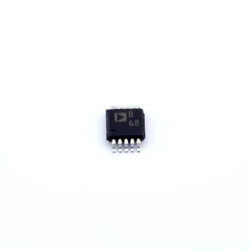
Understanding the AD9833 BRMZ and Common Troubleshooting Challenges
The AD9833BRMZ is a precision programmable waveform generator, capable of producing sinusoidal, triangular, and square wave outputs at frequencies up to 12.5 MHz. This digital-to-analog converter (DAC) is a popular choice for generating arbitrary signals in various applications, including testing, signal simulation, and signal generation in both industrial and research environments. While it is a highly reliable component, users may sometimes experience issues that affect its performance. Identifying and resolving these common problems ensures optimal functionality and prevents frustration.
1. Power Supply Issues: The Root Cause of Many Problems
The first thing to check when troubleshooting the AD9833BRMZ is the power supply. This component operates with a supply voltage of 2.3V to 5.5V, and any deviation from this range can lead to erratic behavior. For instance, if the supply voltage is too low, the AD9833BRMZ may fail to initialize or produce incorrect waveform outputs. On the other hand, an excessively high supply voltage may cause damage to the internal circuitry.
Solution:
Verify the supply voltage using a multimeter. Ensure that the voltage is within the specified range. If you're using a regulated power supply, check that the output is stable. If fluctuations are detected, consider adding a voltage regulator or filter to stabilize the power. Additionally, it’s a good idea to check for proper grounding to avoid voltage instability.
2. Incorrect Configuration of the Control Pins
The AD9833BRMZ has a set of control pins (such as FSYNC, SCLK, SDI, and SDOUT) used for communication with an external microcontroller or processor. Incorrect configuration or wiring of these control pins can lead to issues such as failure to load frequency settings or incorrect waveform generation. For example, if the SDI (Serial Data Input) is not correctly connected to the microcontroller's output, the AD9833BRMZ will not receive any data, leading to no output signal.
Solution:
Double-check your wiring and ensure that all control pins are properly connected. Also, confirm that your microcontroller is correctly configured to communicate with the AD9833BRMZ using the SPI interface . If you're using a breadboard for prototyping, make sure that the connections are secure, as loose connections can sometimes cause intermittent issues.
3. Issues with Clock Signal Input
The AD9833BRMZ requires an external clock signal for accurate waveform generation. If the clock source is unstable or not within the specified range, the output frequencies may be incorrect. Furthermore, an improper clock signal can result in the AD9833BRMZ failing to initialize or produce no output at all.
Solution:
Ensure that the clock signal is clean and stable. If you’re using an external clock generator, verify that it provides a consistent frequency within the required input range of the AD9833BRMZ. If you're relying on a microcontroller to provide the clock signal, check that it’s configured correctly to output a stable clock at the desired frequency.
4. Incorrect Frequency Setting or Register Programming
One common issue with the AD9833BRMZ is improper programming of the frequency registers. The AD9833BRMZ uses a 28-bit register to set the frequency, and if this register is not correctly written to, the output frequency will not match expectations. This could be caused by incorrect values in the register, faulty data transmission, or a programming error in your control code.
Solution:
Check the values being sent to the frequency register and ensure they are within the acceptable range. Use a debugger to step through your code and verify that the correct bits are being written to the appropriate registers. For example, the 28-bit frequency register is split into two 14-bit segments, and both need to be updated correctly for the proper output frequency.
Advanced Troubleshooting and Best Practices for AD9833BRMZ
While the basic troubleshooting steps discussed above resolve many issues, more complex problems may arise, particularly in advanced applications or in noisy environments. To address these, it’s essential to consider some advanced troubleshooting techniques and best practices.
5. Output Signal Quality Problems: Noise and Distortion
One of the most common issues users face is poor signal quality from the AD9833BRMZ. This can manifest as noise, distortion, or unwanted harmonics in the waveform output. A noisy output can be particularly problematic in precision applications, where signal integrity is critical.
Solution:
Decoupling Capacitors : Ensure that decoupling capacitor s are placed as close as possible to the power supply pins (VDD and GND). Typically, a 0.1µF ceramic capacitor and a 10µF electrolytic capacitor are recommended. These capacitors help filter out power supply noise and smooth voltage fluctuations that can affect the performance of the AD9833BRMZ.
PCB Layout Considerations: If you’re designing your own PCB, consider the layout carefully. Keep the analog and digital grounds separate, and route high-speed signals away from sensitive analog lines. Use a solid ground plane to minimize noise coupling and ensure clean signal paths.
6. Temperature Effects on Performance
Temperature can affect the behavior of semiconductor devices, and the AD9833BRMZ is no exception. Extreme temperatures can cause frequency drift, signal attenuation, or even failure to generate a waveform. Temperature variations can also cause the internal components to behave erratically, resulting in less stable outputs.
Solution:
If you expect the AD9833BRMZ to operate in a temperature-sensitive environment, consider implementing thermal management techniques such as heat sinks or temperature compensation algorithms. Additionally, verify that the device is within its specified operating temperature range (–40°C to +85°C) during testing.
7. Signal Integrity in High-Speed Applications
In high-speed applications, the AD9833BRMZ can produce high-frequency waveforms that are susceptible to signal degradation. Issues like ringing, reflections, and crosstalk can occur, especially when driving long cables or operating at the device’s maximum frequency.
Solution:
To address signal integrity issues, use proper transmission line techniques. Ensure that the trace impedance on your PCB matches the source and load impedance to prevent reflections. If you’re using external cables, use coaxial cables with appropriate impedance matching to minimize signal loss and degradation.
8. Software and Code Optimization
Sometimes, the issue isn’t hardware-related but stems from the software or firmware used to control the AD9833BRMZ. If the waveform generator isn’t producing the desired output, it could be due to Timing issues, incorrect register values, or improper communication protocols.
Solution:
Timing and Delays: Ensure that your software correctly accounts for the timing requirements of the AD9833BRMZ. Improper timing can result in missed clock cycles or incorrect register updates.
Code Review: Review your code to verify that the AD9833BRMZ’s SPI protocol is being implemented correctly. It may help to use example code from the manufacturer or community forums to cross-check your implementation.
9. Using the AD9833BRMZ with Other Components
In more complex systems, the AD9833BRMZ may interface with other components such as DACs, filters , amplifiers, or microcontrollers. Interfacing issues, such as incompatible voltage levels or communication mismatches, can result in poor system performance or failure.
Solution:
Ensure that all components in the signal chain are compatible in terms of voltage levels and communication protocols. Use level-shifting circuits if necessary to ensure that signals are properly translated between devices. Additionally, when connecting the AD9833BRMZ to an amplifier or other analog circuits, make sure the output impedance of the waveform generator is matched with the input impedance of the subsequent stage to prevent signal loss or distortion.
10. Testing and Calibration
If you have addressed all the hardware and software issues but still face performance problems, it might be necessary to recalibrate the AD9833BRMZ. Calibration ensures that the device is operating within its specified parameters and can help resolve any subtle inaccuracies that might arise over time.
Solution:
Use an accurate frequency counter or oscilloscope to measure the output frequency. Compare the measured frequency with the expected value based on your register settings. If discrepancies are found, adjust the frequency register or perform a system recalibration to achieve the desired output.
By following these troubleshooting techniques and best practices, you can effectively resolve common issues with the AD9833BRMZ and ensure reliable, high-quality waveform generation in your projects. Whether you’re working on a simple test signal generator or a more complex system, understanding the potential pitfalls and having the right solutions at hand will help you achieve optimal performance.
Partnering with an electronic components supplier sets your team up for success, ensuring the design, production, and procurement processes are quality and error-free.

