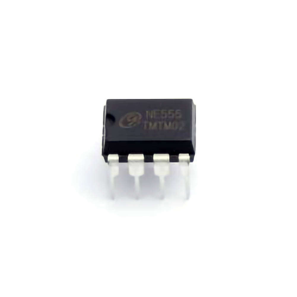
The NE555 timer IC is a versatile and widely-used component in electronics, known for its ability to generate precise pulses and Timing intervals. This article explores the practical applications of the NE555 timer in pulse generation circuits, providing insight into how it works, its diverse uses, and step-by-step guidance on implementing it in your projects.
Introduction to NE555 Timer and Pulse Generation Basics
The NE555 timer IC has long been an essential tool for engineers, hobbyists, and students alike. Its functionality and adaptability make it an ideal component for a variety of timing and pulse generation applications. The primary role of the NE555 is to generate precise time intervals or pulses, which can then be used to drive other parts of a circuit or act as a clock signal. Whether you are designing a simple oscillator, creating pulse-width modulation (PWM) signals, or producing clock pulses for digital circuits, the NE555 timer can help you achieve these goals with ease.
What is the NE555 Timer?
The NE555 timer is a small, integrated circuit (IC) capable of producing accurate and adjustable time delays or pulse outputs. It was first introduced in 1972 by Hans R. Möhler at Signetics (now part of ON Semiconductor) and has since become a cornerstone of digital electronics. Its popularity is attributed to its simplicity, reliability, and low cost. The NE555 timer is typically used in either of two modes: astable and monostable.
Astable Mode: In this mode, the NE555 timer operates as an oscillator, continuously generating a square wave signal. The frequency of the oscillation is determined by external Resistors and capacitor s.
Monostable Mode: In monostable mode, the NE555 timer produces a single pulse of a predetermined length when triggered by an external signal. Once the pulse completes, the timer resets and is ready to trigger another pulse.
Both modes are crucial for pulse generation, and understanding how they work can help you create more complex circuits. In this article, we will primarily focus on pulse generation in both modes and explore how you can use the NE555 timer for practical applications.
How the NE555 Timer Works in Pulse Generation Circuits
The pulse generation function of the NE555 timer is based on its internal architecture. The IC consists of two voltage comparator s, an SR flip-flop, a discharge transistor , and a resistor-capacitor (RC) network. When the timer is configured in astable mode, the capacitor charges and discharges through the external resistors, creating a timing cycle that generates a square wave output.
In monostable mode, when the external trigger input is activated, the capacitor charges up, creating a pulse of a defined width. This pulse width is determined by the values of the resistor and capacitor connected to the IC. In both modes, the output pulse can be used to drive LED s, triggers other logic circuits, or generate clock signals for digital systems.
Applications of the NE555 Timer in Pulse Generation Circuits
The NE555 timer is widely used in applications where precise pulses are required. Below are a few notable examples of its use in pulse generation:
Pulse Width Modulation (PWM): The NE555 timer is commonly employed in PWM circuits, where the pulse width is varied to control the Power delivered to a load, such as in motor speed control or LED brightness regulation.
Frequency Generation: In oscillator circuits, the NE555 timer generates a square wave output that can serve as a clock pulse for digital circuits or as a tone generator in Audio applications.
Pulse Timing: The NE555 timer is also ideal for creating time delays or pulse outputs in timing circuits, such as in alarm systems, metering applications, or sequential timers in automation systems.
Light Flashers and Blinkers: The NE555 timer can be used to generate timed flashing signals for visual indicators, like LED blinkers or light effects.
Tone Generation for Alarms and Sirens: The NE555 timer can generate audio signals of varying frequency, which makes it suitable for alarm systems or sound-effect generators.
Practical Example: Pulse Generation Circuit Using NE555 Timer
Let’s take a detailed look at how the NE555 timer can be used to create a practical pulse generation circuit. We will design a simple square wave oscillator in astable mode and explain its operation, as well as provide a sample application.
Building a Simple NE555 Pulse Generator Circuit
One of the most common applications for the NE555 timer is in the design of pulse generators or oscillators. By configuring the timer in astable mode, we can generate a continuous square wave output at a predetermined frequency. Below is a step-by-step guide to building a basic pulse generation circuit using the NE555 timer.
Materials Needed:
NE555 timer IC
Resistors: 10kΩ, 100kΩ
Capacitor: 10µF
Breadboard
Power supply (5V to 15V)
Oscilloscope (optional for testing)
Jumper wires and a multimeter for testing
Circuit Design:
Connect the NE555 Timer:
Pin 1 (Ground) to the negative rail (GND).
Pin 8 (VCC) to the positive rail (5V to 15V).
Pin 4 (Reset) to VCC to disable the reset function.
Pin 5 (Control voltage) is typically left unconnected or connected to ground via a small capacitor (0.01µF) for noise filtering.
Set Up the Resistor and Capacitor Network:
Connect a 10kΩ resistor from pin 7 (Discharge) to pin 8 (VCC).
Connect a 100kΩ resistor from pin 7 (Discharge) to pin 6 (Threshold).
Place a 10µF capacitor between pin 6 (Threshold) and pin 1 (Ground). This capacitor will control the frequency of the output signal.
Feedback Loop:
Connect pin 2 (Trigger) to pin 6 (Threshold). This forms the feedback loop that enables continuous oscillation.
Output:
Pin 3 (Output) will provide the square wave output. You can connect this pin to an LED (through a current-limiting resistor) or to an oscilloscope to visualize the waveform.
Once this simple circuit is assembled, you can power it up, and the NE555 timer will generate a square wave signal at the output (Pin 3). The frequency of the square wave is determined by the resistor-capacitor (RC) network. The formula for calculating the frequency of the oscillator is:
[
f = \frac{1.44}{(R1 + 2R2)C}
]
Where:
(R1) and (R2) are the resistors (in ohms),
(C) is the capacitor (in farads).
By adjusting the values of the resistors and capacitors, you can modify the output frequency to suit your needs.
Practical Application of Pulse Generation Circuit
Let’s now explore a practical example where a NE555-based pulse generator circuit can be used. Suppose you are building a PWM motor controller for a small DC motor. The PWM signal controls the speed of the motor by varying the duty cycle of the pulse (the ratio of high to low time in each cycle).
Adjusting PWM Duty Cycle: The frequency of the square wave can remain constant, but by adjusting the duty cycle (the width of the high pulse relative to the low pulse), you can control how much power is delivered to the motor. In this case, the NE555 timer’s ability to provide adjustable pulse widths makes it perfect for PWM applications.
LED Blinkers and Flashers: Another application for the NE555 pulse generator is in the design of LED blinkers. By adjusting the timing components (resistors and capacitors), you can set the blink rate for an LED. This type of circuit is commonly used in automotive signaling or decorative lighting effects.
Audio Signal Generation: The NE555 timer can also be used to generate audio signals. In this case, the pulse frequency corresponds to the tone produced by a speaker. By adjusting the frequency, you can produce different tones or even use the circuit as part of a simple siren.
Conclusion
The NE555 timer is a fundamental tool in electronics for pulse generation, timing, and signal modulation. Its versatility, combined with simplicity and low cost, makes it an invaluable component in various applications, including PWM control, frequency generation, and timing circuits. By understanding the working principles of the NE555 timer and how to configure it in different modes, you can unlock a wide range of possibilities in your electronics projects. Whether you are designing a simple LED flasher or building a sophisticated motor controller, the NE555 timer can help bring your ideas to life.
If you are looking for more information on commonly used Electronic Components Models or about Electronic Components Product Catalog datasheets, compile all purchasing and CAD information into one place.


