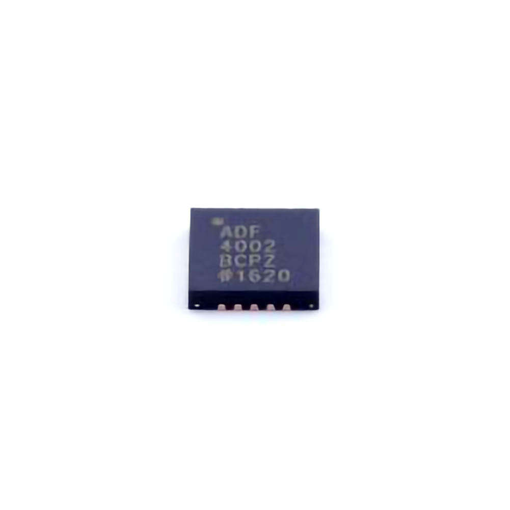
The ADF4002BCPZ is a high-performance frequency synthesizer used in a wide range of applications, from telecommunications to industrial systems. However, like all complex electronic components, users may encounter troubleshooting issues. This article explores common problems with the ADF4002BCPZ, alongside practical solutions to resolve them effectively.
Introduction and Common Troubleshooting Scenarios
The ADF4002BCPZ is a highly specialized frequency synthesizer, designed for precision applications that require accurate and stable frequency generation. As with any advanced electronic component, it can sometimes run into issues that affect its performance. To ensure your device continues to function at its peak, it is essential to recognize common problems and implement effective troubleshooting techniques.
In this first part, we will discuss the most frequent issues users encounter with the ADF4002BCPZ and provide a clear path toward identifying and resolving these challenges.
1. Power Supply Issues
One of the most common reasons for failure in the ADF4002BCPZ is an unstable or insufficient power supply. The device operates at a supply voltage of 3.3V, and even minor deviations from this value can lead to malfunctioning. An inadequate power supply can cause unstable output signals or complete non-operation.
Solution:
Check the voltage: Use a multimeter to verify that the voltage supplied to the ADF4002BCPZ is stable and meets the recommended 3.3V.
Inspect power rails: Ensure that the power rails are clean and do not have excessive noise or ripple. A high-quality low-noise regulator should be used to supply power to the chip.
Add filtering: Implement proper decoupling capacitor s close to the power pins of the ADF4002BCPZ. Typically, 0.1µF and 10µF ceramic capacitors are recommended to filter high-frequency noise effectively.
2. Incorrect Input Clock Signal
The ADF4002BCPZ relies on an input clock signal to perform its frequency synthesis. An unstable or incorrect clock input is another common issue that may cause the device to fail or output inaccurate frequencies. The clock signal must meet the specifications set by the manufacturer, including amplitude, waveform, and frequency.
Solution:
Verify input signal: Ensure that the input clock signal is within the recommended range in terms of amplitude and frequency. A signal with inadequate amplitude or poor waveform quality can lead to improper synthesis.
Check for signal conditioning: Use an oscilloscope to confirm that the clock signal is free from noise and distortion. If necessary, use a signal conditioner or buffer to improve the quality of the input clock.
3. Output Signal Problems
One of the most critical functions of the ADF4002BCPZ is its ability to produce a clean, stable output frequency. If users notice unexpected behavior such as incorrect frequencies, spurious signals, or poor signal integrity, these are indicative of issues within the output stage.
Solution:
Verify output frequency: Use a frequency counter or a spectrum analyzer to measure the output frequency and compare it against the expected values.
Check for load conditions: Ensure that the output of the ADF4002BCPZ is not heavily loaded, as this can degrade performance. The output should ideally drive a low impedance load.
Look for signal distortions: If the output signal appears distorted or noisy, check the external components such as filters and amplifiers connected to the output for issues.
4. Interfacing Issues with Microcontrollers or PLLs
Many applications involving the ADF4002BCPZ require it to interface with microcontrollers or other phase-locked loops (PLLs). Poor communication between these systems can result in erratic behavior or failure to achieve the desired frequency output.
Solution:
Double-check control logic: Ensure that the control signals (like the CE, LE, and DATA pins) are correctly connected to the microcontroller or external PLL circuit. Verify that the logic levels are appropriate for the ADF4002BCPZ’s input requirements.
Check timing and synchronization: Confirm that the timing of control signals matches the specifications in the datasheet. Use a logic analyzer to troubleshoot signal timing issues.
Review programming interface: If using a software interface to control the ADF4002BCPZ, ensure that the programming commands are correct and that the communication protocol is error-free.
Advanced Troubleshooting Techniques and Tips
After covering the more common issues in Part 1, we now dive into advanced troubleshooting techniques. These solutions are geared toward users who may still experience difficulties even after addressing the basic concerns. By using specialized tools and performing in-depth diagnostics, you can enhance the performance of the ADF4002BCPZ and resolve more complex issues.
1. Temperature Variations and Stability
The ADF4002BCPZ, like all electronic components, is sensitive to temperature fluctuations. When the operating temperature exceeds the specified limits, it can result in frequency drift, signal instability, or complete failure to function.
Solution:
Monitor temperature: Use an infrared thermometer or a thermocouple sensor to monitor the temperature of the ADF4002BCPZ during operation. If the temperature is too high, ensure that there is adequate cooling or thermal management.
Use temperature-compensated components: If your application requires the device to operate in extreme conditions, consider using temperature-compensated components or even a temperature-controlled environment to maintain performance.
2. Incorrect or Missing Reference Oscillator
The ADF4002BCPZ requires a reference oscillator to produce accurate and stable output frequencies. If the reference oscillator is malfunctioning or absent, the device will not function correctly. This is especially important in applications requiring precise frequency control.
Solution:
Verify the reference oscillator: Check the reference oscillator circuitry to ensure it is producing the correct frequency and that it is stable. Use an oscilloscope to examine the waveform and amplitude.
Inspect the crystal: If using a crystal oscillator, verify the component’s specifications and ensure it matches the requirements for the ADF4002BCPZ. A mismatched crystal can lead to inaccurate frequency output.
Replace faulty components: If the reference oscillator is defective, replace it with a known good unit and test the system again.
3. Spurious Signals and Harmonics
Spurious signals and harmonic distortion can significantly degrade the output performance of the ADF4002BCPZ, leading to noisy or unstable outputs. These can arise from various factors, including poor grounding, improper shielding, or poor PCB layout.
Solution:
Improve PCB layout: Ensure that your PCB layout minimizes noise coupling by keeping high-speed signal traces away from sensitive components and using proper ground planes.
Use shielding: Shield the ADF4002BCPZ and its associated circuitry to minimize electromagnetic interference ( EMI ). This is especially important in high-frequency applications where EMI can cause significant disruptions.
Check for parasitic components: Minimize parasitic inductance and capacitance in the signal paths by optimizing the PCB routing and ensuring proper component placement.
4. Firmware and Configuration Errors
Sometimes the issue lies not with the hardware but with the firmware or configuration settings. Misconfiguration of the PLL or incorrect register settings can lead to improper frequency synthesis.
Solution:
Review the datasheet: Carefully review the ADF4002BCPZ datasheet to ensure that the PLL configuration registers are set correctly for your application.
Test with known settings: Start with known working settings and incrementally modify them to identify which configuration causes issues. This step-by-step approach can help isolate the problem.
Consult the software tools: If using software tools to configure the ADF4002BCPZ, ensure that the correct algorithms and configurations are applied, and verify their compatibility with your setup.
5. External Interference and Grounding Issues
Electrical noise from nearby equipment or poor grounding practices can introduce interference into the ADF4002BCPZ’s operation, leading to performance degradation or complete failure.
Solution:
Improve grounding: Ensure that the device’s ground connections are solid and free from noise. Use a star grounding technique if necessary, and avoid running high-current traces near sensitive areas.
Isolate sources of interference: Shield your system from external electromagnetic interference (EMI) by using ferrite beads , shielding enclosures, or careful routing of signal traces away from noisy components.
Conclusion
The ADF4002BCPZ is a powerful frequency synthesizer, but like all complex components, it may experience issues due to various factors. By identifying common problems—such as power supply issues, clock signal integrity, output signal quality, and external interference—you can ensure that your device operates reliably. Moreover, advanced troubleshooting techniques, including temperature control, careful PCB layout, and correct configuration, will help you resolve even more challenging problems.
By following the steps outlined in this article, you can troubleshoot and fix most issues related to the ADF4002BCPZ, ensuring optimal performance in your applications. Always consult the datasheet and manufacturer guidelines to get the most out of your frequency synthesizer and maintain a robust, reliable system.
If you are looking for more information on commonly used Electronic Components Models or about Electronic Components Product Catalog datasheets, compile all purchasing and CAD information into one place.
Partnering with an electronic components supplier sets your team up for success, ensuring the design, production, and procurement processes are quality and error-free.


