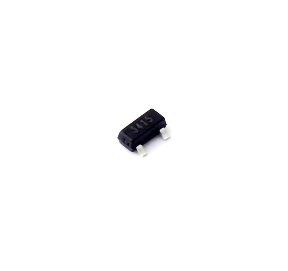
Understanding the AO3415 and Common Issues
The AO3415 is a high-performance component that plays a crucial role in various applications, including Power Management systems, industrial electronics, and more. However, like any piece of technology, it can encounter problems from time to time. In this part of the article, we’ll explore some of the most common issues users face with the AO3415 and provide you with effective troubleshooting techniques to resolve them.
1.1 The AO3415 Overview: A Quick Introduction
Before diving into troubleshooting, it's essential to understand the AO3415's key functions and components. The AO3415 is typically a low-power N-channel MOSFET (Metal Oxide S EMI conductor Field-Effect Transistor), often used in applications such as DC-DC converters, power management systems, and other switching technologies. Its primary function is to regulate current flow in electronic circuits while providing efficient energy management.
The AO3415’s small size and high-efficiency design make it an attractive option for applications requiring energy efficiency and compact space. However, due to its specific characteristics, users may face certain operational challenges. Let’s take a look at some of the most common issues associated with this component.
1.2 Common Problems with the AO3415
1.2.1 Overheating and Excessive Heat Generation
One of the most frequent complaints about the AO3415 is overheating. MOSFETs , especially those used in power management systems, can generate heat during operation. While the AO3415 is designed to manage heat efficiently, improper usage, insufficient cooling, or poor Thermal Management can lead to excessive heat buildup.
Symptoms:
The MOSFET becomes noticeably hot to the touch.
Reduced performance or erratic behavior in the circuit.
Frequent thermal shutdown or failure to operate.
Possible Causes:
Inadequate cooling: If the device is not properly ventilated, heat may not dissipate efficiently.
Incorrect placement: If the MOSFET is placed in an environment with high ambient temperatures, heat management becomes more challenging.
High current draw: If the MOSFET is subjected to currents above its rated specifications, it may overheat.
Solution:
Ensure proper heat dissipation by attaching a heatsink or improving airflow around the component.
Review the circuit design to ensure the AO3415 is not being overdriven. Consider using a MOSFET with a higher current rating if necessary.
Reduce ambient temperature or relocate the device to a cooler environment.
1.2.2 Failure to Switch Properly
Another issue users face with the AO3415 is its failure to switch properly between its on and off states. The MOSFET’s gate voltage plays a crucial role in its operation, and improper gate drive can lead to inefficient switching or total failure.
Symptoms:
The MOSFET remains stuck in the “on” or “off” position.
Inconsistent performance, such as intermittent switching.
Circuit failure or voltage spikes.
Possible Causes:
Incorrect gate voltage: The MOSFET may not receive the appropriate voltage to fully turn on or off.
Faulty driver circuit: The gate driver may be malfunctioning, preventing the MOSFET from switching correctly.
Damaged component: A damaged gate or source/drain connection can lead to persistent faults.
Solution:
Verify that the gate voltage is within the recommended range for proper switching (usually specified in the datasheet).
Check the gate driver circuit for faults or misconfigurations.
Test the MOSFET with a multimeter to check for damage. If it’s faulty, replace it with a new component.
1.2.3 Short Circuit or Overcurrent Protection Issues
MOSFETs like the AO3415 are designed with certain protections in place, such as current limiting or thermal shutdown features. However, these protections may fail or be triggered incorrectly, leading to circuit failures or disruptions.
Symptoms:
The circuit fails to power up.
Overcurrent or short-circuit protection kicks in too early or without cause.
The AO3415 is constantly in a state of shutdown or protection mode.
Possible Causes:
External short circuit: A short circuit in the wiring or the load can trigger overcurrent protection.
Incorrect current sensing: The current sensing circuit may be miscalibrated, leading to false overcurrent signals.
Faulty MOSFET: A damaged MOSFET may cause it to behave erratically, triggering internal protection mechanisms.
Solution:
Inspect the entire circuit for shorts or improper connections that could trigger the overcurrent protection.
Calibrate the current sensing circuit to ensure it detects actual overcurrent conditions accurately.
If the MOSFET shows signs of physical damage or improper behavior, replace it and test the circuit again.
1.2.4 Signal Interference and Noise
Signal interference is another issue that can affect the AO3415’s performance, especially in high-speed or noisy environments. Noise can disrupt the MOSFET’s switching process, leading to erratic behavior or complete failure.
Symptoms:
Random or unpredictable switching behavior.
Increased EMI (electromagnetic interference).
Voltage spikes or irregular output from the circuit.
Possible Causes:
Electromagnetic interference: External noise from nearby devices or components can induce unwanted voltages in the circuit.
Inadequate filtering: Lack of proper filtering in the circuit may result in noise reaching the gate of the MOSFET.
Grounding issues: Poor grounding can lead to unwanted noise or voltage spikes.
Solution:
Add additional decoupling capacitor s or improve the filtering around the MOSFET’s gate to block noise.
Ensure the circuit has proper grounding to minimize the impact of EMI.
If the issue persists, consider shielding the circuit or relocating it away from sources of interference.
Advanced Troubleshooting and Preventative Measures
Now that we've covered the common problems faced with the AO3415, let’s dive deeper into advanced troubleshooting methods and preventative measures you can take to ensure the optimal performance of your AO3415 components.
2.1 Detailed Troubleshooting Procedures
When the basic troubleshooting steps don’t resolve your issues, more advanced diagnostic methods are required. Here are some strategies you can implement to get to the root cause of persistent problems.
2.1.1 Use of Oscilloscopes to Monitor Switching Behavior
If your AO3415 is not switching as expected, an oscilloscope can be a valuable tool for diagnosing the problem. By observing the gate voltage waveforms, you can determine whether the MOSFET is receiving the correct gate drive and if it is switching as intended.
Procedure:
Connect the oscilloscope probes to the gate and drain pins of the MOSFET.
Monitor the gate voltage as the circuit operates. The gate voltage should rise and fall within a specific time frame, corresponding to the switching action.
Look for irregularities such as slow switching times or missing transitions, which may indicate a gate drive issue or faulty component.
2.1.2 Checking the Thermal Characteristics with Infrared Cameras
For issues related to overheating, using an infrared (IR) camera can help you identify hotspots on the AO3415 and surrounding components. This will allow you to pinpoint areas where heat may be building up due to inadequate cooling or high current draw.
Procedure:
Use the IR camera to scan the board while it’s operating.
Look for abnormal temperature spikes, particularly around the AO3415’s source, drain, and gate regions.
Compare the thermal profile with the specifications in the datasheet. If the temperature is exceeding recommended limits, review the cooling methods.
2.1.3 Inspecting the Power Supply Voltage
Incorrect power supply voltage can also affect the performance of the AO3415. Ensure that the power supply is stable and within the operating range for the component.
Procedure:
Use a multimeter or oscilloscope to check the input voltage to the AO3415.
Ensure the voltage is within the recommended range and is stable under load.
If there are significant fluctuations, investigate the power supply or the decoupling capacitors in the circuit.
2.2 Preventative Measures to Avoid AO3415 Issues
In addition to troubleshooting, there are several preventative measures you can implement to minimize the risk of encountering issues with the AO3415.
2.2.1 Proper Circuit Design
One of the best ways to avoid common issues with the AO3415 is by ensuring that the circuit design is optimized for this component. Pay attention to the following aspects during the design phase:
Gate Drive Requirements: Ensure that the gate voltage is sufficient to fully turn the MOSFET on and off. Inadequate gate drive can result in partial switching, increasing heat generation.
Thermal Management: Design the circuit with adequate heat sinking, or use MOSFETs with lower R_DS(on) to minimize power loss and heat generation.
Current Protection: Implement proper current sensing and protection circuits to avoid overloading the MOSFET.
2.2.2 Regular Maintenance and Inspections
Even if your AO3415 is operating smoothly, it's a good idea to perform regular inspections and maintenance:
Inspect connections: Ensure that all pins and connections are secure and free from corrosion.
Test switching: Regularly test the switching behavior of the MOSFET using an oscilloscope.
Monitor temperature: Periodically check the temperature of the MOSFET to ensure it’s operating within safe limits.
2.2.3 Use of Quality Components
Finally, the quality of your components plays a significant role in ensuring long-term reliability. Always source your AO3415 from reputable manufacturers or distributors to avoid counterfeit or substandard components, which may be more prone to failure.
In conclusion, while the AO3415 is a reliable and efficient MOSFET, issues such as overheating, switching failures, and protection faults can still occur. By employing effective troubleshooting techniques and implementing preventative measures, you can ensure that your AO3415 operates efficiently and reliably for years to come.
If you are looking for more information on commonly used Electronic Components Models or about Electronic Components Product Catalog datasheets, compile all purchasing and CAD information into one place.
Partnering with an electronic components supplier sets your team up for success, ensuring the design, production, and procurement processes are quality and error-free.

