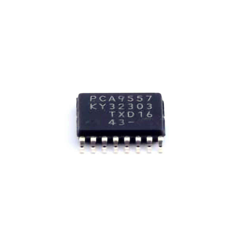
Understanding the PCA9557PW I/O Expander
The PCA9557PW is a popular I/O expander chip designed by NXP Semiconductors, and it serves as an interface between a microcontroller (MCU) or a processor and external devices. By using I2C Communication , the PCA9557PW provides a simple and efficient way to expand the number of digital input/output (I/O) pins available to your system. It allows you to control up to 16 I/O pins using just two communication lines: SDA (Serial Data) and SCL (Serial Clock ). The chip supports both input and output modes, making it ideal for applications where you need more I/O pins than your microcontroller can directly support.
However, like any other electronic component, the PCA9557PW is not immune to issues. As with many I2C-based devices, users may experience communication failures, incorrect readings, or erratic behavior in their projects. This article aims to provide you with an overview of common problems associated with the PCA9557PW and the best troubleshooting steps to resolve them.
1. Power Supply Issues
A reliable power supply is crucial for any electronic component, and the PCA9557PW is no exception. Power-related issues can result in erratic operation, communication failures, or the inability to initialize the chip. The PCA9557PW operates on a supply voltage range from 2.3V to 5.5V, and it’s essential to ensure that the voltage supplied is within this range.
Troubleshooting Steps:
Check the Voltage: Use a multimeter to verify that the supply voltage to the PCA9557PW is stable and within the recommended range.
Check Power Connections: Ensure that the VCC pin is properly connected to the power source and that the GND pin is connected to ground.
Use a Decoupling capacitor : Power supply noise can interfere with the chip’s performance. Place a small decoupling capacitor (0.1µF) between the VCC and GND pins to reduce voltage spikes or noise.
2. I2C Communication Failure
The PCA9557PW communicates with the microcontroller via the I2C bus, and a failure in communication can prevent proper interaction with the device. There are several potential causes for I2C communication issues, including incorrect addressing, improper pull-up Resistors , and faulty wiring.
Troubleshooting Steps:
Verify I2C Address: The PCA9557PW uses a 7-bit I2C address. Make sure that the address is correctly configured in your code and matches the actual address of the chip on the I2C bus.
Check Pull-up Resistors: I2C communication requires pull-up resistors on the SDA and SCL lines. Ensure that resistors with values between 4.7kΩ and 10kΩ are connected to both lines.
Check Wiring: Ensure that the SDA and SCL lines are correctly connected between the microcontroller and the PCA9557PW. Any loose or disconnected wires could lead to communication failure.
Test with an I2C Scanner: Use an I2C scanner program to detect connected I2C devices on the bus. This can help identify whether the PCA9557PW is being recognized properly by the microcontroller.
3. Incorrect GPIO Configuration
The PCA9557PW has 16 GPIO pins that can be configured as either input or output. If the GPIO pins are not properly configured in your code, you may encounter issues such as pins not responding or behaving erratically.
Troubleshooting Steps:
Check GPIO Direction: Ensure that the GPIO direction is correctly configured in the register. Pins set as inputs should be set to high-impedance, while pins set as outputs should be able to drive a logic high or low.
Check Register Settings: Review the register settings for the GPIO pins to ensure that they match the desired configuration. A mistake in the configuration could result in incorrect behavior.
Verify Pin States: Use an oscilloscope or a logic analyzer to check the actual output states of the GPIO pins and verify that they match the intended configuration.
4. Input Pin Debouncing
When using the PCA9557PW as an input expander, noisy or bouncing signals from mechanical switches or relays can cause false triggering and incorrect readings. This issue is known as "switch bounce," and it can be a common problem when using mechanical buttons or switches with digital inputs.
Troubleshooting Steps:
Add a Software Debounce: Implement a debounce algorithm in your microcontroller code to filter out spurious signals from mechanical switches.
Use External Hardware Debouncing: You can also use an external capacitor or a Schmitt trigger to help clean up noisy input signals.
Use Pull-up or Pull-down Resistors: Ensure that input pins are properly terminated with pull-up or pull-down resistors to maintain a defined logic state when no signal is present.
Advanced Troubleshooting and Solutions for the PCA9557PW
As with any complex I2C device, there can be additional layers of troubleshooting required when the standard checks don't resolve the issue. In this section, we'll delve into more advanced troubleshooting steps for common problems with the PCA9557PW.
5. Chip Initialization Problems
When the PCA9557PW is first powered on or reset, it may fail to initialize properly due to incorrect sequencing of initialization commands or timing issues.
Troubleshooting Steps:
Check Initialization Sequence: Ensure that your code correctly follows the PCA9557PW initialization sequence. Incorrect or missing initialization steps may result in the device not functioning as expected.
Check Reset Pin: The reset pin of the PCA9557PW (pin 7) may need to be manually pulled low to reset the device. If you're encountering initialization issues, try toggling this pin and reinitializing the chip.
Allow Adequate Power-Up Time: After powering on the system, allow enough time for the PCA9557PW to stabilize before issuing commands to it.
6. Incorrect Output Levels or Driving Capability
In some cases, you may find that the PCA9557PW output pins do not behave as expected, either failing to drive the desired voltage or drawing too much current. The PCA9557PW is designed to provide open-drain outputs, so it requires external pull-up resistors to drive high-level logic.
Troubleshooting Steps:
Ensure Proper Pull-up Resistors: As previously mentioned, the PCA9557PW requires pull-up resistors on output pins for proper operation. If these resistors are missing or incorrectly sized, the output levels may not reach the expected values.
Check Output Current Requirements: If you're driving external components from the output pins, make sure the output current requirements of those components are within the PCA9557PW's specifications. The chip can drive up to 10mA per pin, but exceeding this limit can cause erratic behavior.
7. Address Conflicts in Multi-Device Systems
When using multiple I2C devices on the same bus, address conflicts can occur, resulting in communication issues or malfunctioning devices. If two devices have the same I2C address, they will both attempt to respond to the same commands, leading to data corruption or failure.
Troubleshooting Steps:
Assign Unique Addresses: Ensure that each device on the I2C bus has a unique address. The PCA9557PW allows for address modification by tying the A0, A1, and A2 pins to logic high or low. If multiple PCA9557PW devices are being used, configure each device with a unique address.
Use an I2C Multiplexer: In cases where address conflicts are unavoidable, consider using an I2C multiplexer to switch between devices on the same bus.
8. Overheating or Thermal Runaway
While the PCA9557PW is a low-power device, overheating can still occur if it is driven beyond its operating limits, especially when there is excessive current draw or inadequate heat dissipation.
Troubleshooting Steps:
Monitor Temperature: Use a thermal sensor or infrared thermometer to check the temperature of the PCA9557PW during operation. If the chip is running too hot, consider improving the cooling system or reducing the load on the device.
Ensure Proper Ventilation: In cases where the PCA9557PW is used in a high-density environment or enclosed casing, make sure there is enough ventilation to allow heat dissipation.
9. Test with an External Oscilloscope or Logic Analyzer
If you’ve gone through the basic and advanced troubleshooting steps and the problem persists, using an oscilloscope or a logic analyzer can provide deeper insight into the issue. These tools allow you to monitor the behavior of I2C signals and GPIO pin states in real-time.
Troubleshooting Steps:
Monitor SDA and SCL Lines: Use the oscilloscope to monitor the signals on the SDA and SCL lines to detect issues with communication, such as timing problems or data corruption.
Verify Logic Levels: Ensure that the logic levels on the I/O pins match the expected high and low voltages as per the device’s datasheet.
By following these troubleshooting steps and solutions, you can address the most common issues encountered with the PCA9557PW I/O expander. This guide aims to equip you with the knowledge to solve problems efficiently and keep your projects running smoothly. Remember that the key to successful troubleshooting is patience, methodical testing, and understanding the intricacies of the hardware you are working with.
If you are looking for more information on commonly used Electronic Components Models or about Electronic Components Product Catalog datasheets, compile all purchasing and CAD information into one place.
Partnering with an electronic components supplier sets your team up for success, ensuring the design, production, and procurement processes are quality and error-free.


