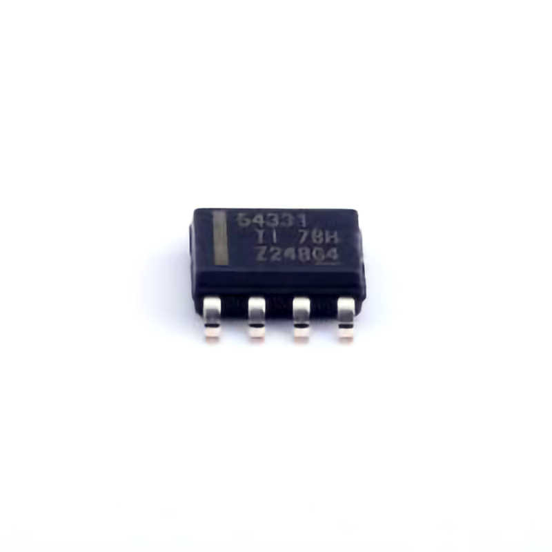
Introduction to the TPS54331DDAR and Its Key Features
Switching Power supplies are indispensable in modern electronic systems, powering everything from consumer electronics to industrial equipment and communication devices. When designing efficient power conversion solutions, choosing the right buck converter becomes crucial. One of the most effective and widely used components in this regard is the TPS54331DDAR from Texas Instruments (TI).
The TPS54331DDAR is a synchronous buck converter that is designed to provide high efficiency and reliable performance in a variety of applications. Operating with an input voltage range of 4.5V to 60V, it can deliver an output voltage as low as 0.8V with a maximum output current of 3A. The device is perfect for applications where space and efficiency are at a premium, such as in industrial control systems, automotive electronics, Telecom equipment, and more.
Key Features of the TPS54331DDAR
High Efficiency: One of the most important features of the TPS54331DDAR is its high efficiency, which is typically over 90%. This helps minimize power losses and heat generation, making it ideal for systems where power dissipation must be controlled.
Wide Input Voltage Range: With an input range from 4.5V to 60V, the TPS54331DDAR is versatile enough to accommodate a wide range of power sources, including battery-powered systems and industrial DC voltage rails.
Adjustable Output Voltage: The TPS54331DDAR allows for precise control over the output voltage, making it flexible enough to support various system requirements. The feedback voltage is set to 0.8V, but it can be adjusted using external resistors to achieve the desired output voltage.
Integrated Synchronous Rectifier: The device features an integrated synchronous rectifier, which enhances efficiency by reducing conduction losses typically associated with external diodes in traditional buck converters.
Overcurrent and Overvoltage Protection: To ensure system reliability, the TPS54331DDAR includes comprehensive protection features, including overcurrent protection, thermal shutdown, and undervoltage lockout. These protections help safeguard the device and the overall system from potential damage.
Compact Package: The TPS54331DDAR is available in a compact, thermally efficient QFN-16 package, which helps reduce the overall footprint in designs where board space is limited.
Applications of TPS54331DDAR
Given its impressive feature set, the TPS54331DDAR is suitable for a wide variety of applications. Some of the key fields where this buck converter excels include:
Automotive Power Systems: The TPS54331DDAR can be used in automotive electronics to convert the vehicle’s 12V or 24V power rails down to the lower voltages needed by various subsystems, such as sensors, microcontrollers, and communication module s.
Industrial Control Systems: In industrial applications, this buck converter can be utilized to power logic circuits, sensors, and actuators, offering a stable, efficient voltage conversion solution even in harsh environments.
Telecom Equipment: The device is ideal for powering communication systems, providing a robust and efficient DC-DC conversion from a variety of input voltages, including those typically found in telecom infrastructure.
Battery-Powered Devices: With its low quiescent current and high efficiency, the TPS54331DDAR is particularly suited for battery-powered devices where extended battery life is a priority.
In the following sections, we will discuss practical circuit design examples that show how to integrate and optimize the TPS54331DDAR in various power supply applications.
Practical Circuit Design Examples Using TPS54331DDAR
Now that we have explored the key features and applications of the TPS54331DDAR, let’s dive into specific circuit design examples that illustrate how this buck converter can be implemented in real-world systems.
Example 1: Simple 12V to 5V DC-DC Converter
One of the most common applications for the TPS54331DDAR is converting a 12V DC input to a stable 5V DC output, which is ideal for powering logic circuits, sensors, or low-power microcontrollers.
Design Requirements:
Input Voltage: 12V
Output Voltage: 5V
Output Current: 1.5A (for powering small logic circuits)
Efficiency: As high as possible
Design Steps:
Selecting Feedback Resistor Network: To achieve a 5V output, we need to adjust the feedback resistors according to the formula:
[
V{out} = V{ref} \times \left( 1 + \frac{Rf}{Rg} \right)
]
Where (V{ref}) is 0.8V (the internal reference voltage of the TPS54331DDAR). For a 5V output, we can choose resistor values that set the ratio between (Rf) (the feedback resistor) and (R_g) (the ground resistor) to achieve the desired output.
Inductor Selection: The inductor value will depend on the output current and switching frequency. In this case, an inductor with a value of around 22µH to 33µH is typically suitable for achieving good performance in terms of ripple current and efficiency.
capacitor Selection: The TPS54331DDAR requires input and output capacitors for stable operation. For the input, a 10µF ceramic capacitor should suffice, and for the output, a 22µF ceramic capacitor is typically recommended to ensure low output voltage ripple.
Verification and Simulation: After selecting the components, the next step is to verify the design through simulation tools, such as TI’s WEBENCH® Power Designer. This tool helps optimize the component choices and ensures that the design meets the required efficiency and performance specifications.
PCB Layout Considerations: When laying out the PCB, it’s important to minimize the path between the input and output capacitors, as well as to ensure a solid ground plane to reduce noise and improve the stability of the converter.
After following these steps, the resulting circuit will efficiently convert the 12V input into a stable 5V output at up to 1.5A with high efficiency.
Example 2: High-Efficiency 48V to 12V Power Supply for Telecom Equipment
In telecom equipment, a 48V input is common, and the need for a stable 12V output is typical for powering systems like FPGA s, processors, and communication modules. Let’s explore how the TPS54331DDAR can be used in this scenario.
Design Requirements:
Input Voltage: 48V
Output Voltage: 12V
Output Current: 2A (to power telecom circuits)
Efficiency: Minimize power loss
Design Steps:
Selecting Feedback Resistor Network: Using the same feedback voltage formula, we can choose resistors that will scale the output to 12V. With a reference voltage of 0.8V, the required resistor ratio will be:
[
\frac{Rf}{Rg} = \frac{V{out}}{V{ref}} - 1 = \frac{12}{0.8} - 1 = 14
]
Inductor and Capacitor Selection: A higher input voltage like 48V requires careful attention to inductor and capacitor choices. Typically, a 47µH inductor and 47µF output capacitor are selected to handle the higher power and ensure good ripple performance. For the input, a 10µF ceramic capacitor is still adequate.
Efficiency Optimization: The TPS54331DDAR’s integrated synchronous rectification helps reduce power losses compared to traditional diode-based buck converters. Furthermore, selecting low ESR capacitors and optimizing the layout for minimal parasitic resistance will further improve efficiency.
Thermal Management : With higher input voltages, heat generation can be an issue, especially at higher output currents. Therefore, a copper-filled PCB with good thermal vias should be used to dissipate heat effectively. Additionally, considering the use of larger or extra capacitors may help reduce ripple, which could also lower thermal stress.
Simulation and Testing: Before finalizing the design, simulation tools like WEBENCH® can provide insights into efficiency, ripple, and thermal performance. It’s also important to test the prototype under real conditions to verify that the design meets performance expectations.
By following these steps, you’ll have an efficient, high-power solution for powering telecom systems from a 48V input.
Conclusion
The TPS54331DDAR is a powerful and flexible synchronous buck converter that can be applied to a wide range of power supply designs. Whether you are powering industrial sensors, automotive electronics, or telecom equipment, the TPS54331DDAR offers a reliable, high-efficiency solution with a wide input voltage range and adjustable output voltage. By understanding the key design considerations and following best practices for component selection and layout, you can create optimal designs that meet your specific power conversion needs.
By exploring the examples above, we have highlighted the versatility and performance of this chip in practical applications. With the right components, careful layout, and simulation tools, engineers can maximize efficiency and reliability in their power supply designs, ensuring long-term system performance.
If you are looking for more information on commonly used Electronic Components Models or about Electronic Components Product Catalog datasheets, compile all purchasing and CAD information into one place.


