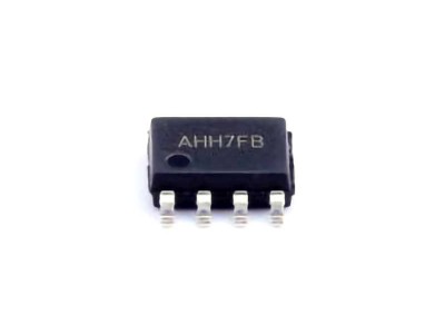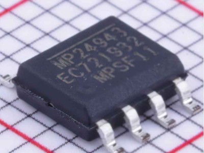
The VNI4140KTR is a popular integrated circuit used for motor control and power management applications. However, like all electronic components, it can encounter issues that may affect its performance. This article provides a detai LED overview of common troubleshooting scenarios and solutions for the VNI4140KTR, ensuring smooth operation in your systems.
VNI4140KTR, troubleshooting, solutions, power management, motor control, electronics, IC issues, diagnostics, VNI4140KTR troubleshooting guide, motor control IC
Introduction to VNI4140KTR and Common Issues
The VNI4140KTR is a versatile integrated circuit (IC) designed by STMicroelectronics for controlling high-power systems such as motors, LED s, and other loads. It is an essential component in various applications ranging from automotive systems to industrial machinery. However, like any complex electronic component, the VNI4140KTR can encounter problems that may affect system performance. Knowing how to troubleshoot these issues is vital for maintaining system reliability.
What is the VNI4140KTR?
The VNI4140KTR is a high-side driver with integrated protection features, specifically designed for automotive and industrial applications. It can drive high-power loads with low Rds(on) (drain-to-source resistance), providing efficient control for motor systems and other high-voltage devices. Key features of the VNI4140KTR include:
Overcurrent and thermal protection: Ensures safe operation under varying load conditions.
Overvoltage and undervoltage shutdown: Protects against power supply irregularities.
Diagnostics: Built-in fault reporting for quick identification of issues.
High-side switching: Ideal for applications where the load is on the high side of the power supply.
Despite its robust design, users may encounter problems that prevent the VNI4140KTR from functioning optimally. Common issues include improper voltage levels, faulty wiring, or thermal overloads.
Common Troubleshooting Scenarios
Before delving into specific solutions, let’s review some of the most common issues you might face when working with the VNI4140KTR:
No Output or Low Output Voltage
If the IC is not supplying sufficient voltage to the connected load, there may be an issue with the input control signal, or the IC could be in thermal shutdown.
Overheating or Thermal Shutdown
The VNI4140KTR features integrated thermal protection, which shuts down the IC if the junction temperature exceeds safe limits. Overheating may occur due to excessive current draw or inadequate cooling.
Overcurrent Faults
If the VNI4140KTR detects an overcurrent situation, it will disable output to protect the system. Overcurrent faults can result from motor stall, short circuits, or too high of a load.
Undervoltage or Overvoltage Conditions
The IC includes voltage protection mechanisms. If the supply voltage falls below or exceeds a specific threshold, the IC will shut down to protect the device.
Faulty Diagnostics or Incorrect Fault Reporting
Misleading diagnostic signals can lead to confusion about the actual state of the system. Fault signals must be correctly interpreted to identify the root cause of an issue.
Understanding the Diagnostic Features of VNI4140KTR
One of the key strengths of the VNI4140KTR is its built-in diagnostic system. The IC can provide feedback on several parameters, including:
Overtemperature status
Overcurrent status
Undervoltage or overvoltage warnings
Load status and control signals
These diagnostics can be accessed through dedicated pins, allowing users to gain insight into the operational state of the IC. However, misinterpretation of diagnostic signals or failure to correctly interface with the diagnostic pins can sometimes lead to incorrect troubleshooting. Therefore, understanding how to properly use these features is essential for effective troubleshooting.
Troubleshooting Solutions and Step-by-Step Guide
Now that we’ve covered common issues and diagnostic features, let’s move on to some practical solutions for the most frequent problems encountered with the VNI4140KTR.
1. No Output or Low Output Voltage
When the VNI4140KTR fails to deliver the expected output voltage or provides a significantly lower voltage than required, the following steps can help identify the cause:
Check Input Control Signals: The VNI4140KTR requires a valid control signal (logic-level input) to activate the output. Ensure the input signal is within the specified voltage range and properly connected.
Verify Supply Voltage: Ensure that the power supply voltage is within the recommended operating range. A drop in supply voltage may result in lower-than-expected output.
Check for Thermal Shutdown: If the IC is overheating, it will enter a thermal protection state. Measure the junction temperature (if accessible) or check the fault diagnostic output. If overheating is detected, reduce the load or improve ventilation.
Inspect Load Connections: A faulty load can cause voltage drops or prevent the IC from delivering the correct output. Inspect the wiring and connections to the load, and ensure that it is within the IC's specified rating.
2. Overheating or Thermal Shutdown
Thermal shutdown is a protective feature that prevents the VNI4140KTR from being damaged due to excessive temperatures. If you experience overheating or thermal shutdown, follow these steps:
Measure the Junction Temperature: Use a thermal sensor or infrared thermometer to check the temperature of the IC. If it exceeds the maximum specified temperature (typically 150°C), the IC will shut down.
Reduce the Load Current: Excessive load current is a common cause of thermal issues. If the load draws more current than the IC can handle, it will trigger thermal shutdown. Try reducing the load or using a larger heatsink to improve heat dissipation.
Improve Cooling: Ensure the IC is adequately cooled, either by enhancing airflow or using better thermal management techniques like adding heatsinks or improving PCB layout for heat dissipation.
Check for Short Circuits: A short circuit or excessive load can cause a rapid increase in temperature. Inspect the circuit for any short circuits or wiring issues that could lead to higher currents.
3. Overcurrent Faults
Overcurrent protection is a critical feature of the VNI4140KTR. When the IC detects an overcurrent, it will disable the output to protect the system. Here's how to troubleshoot this issue:
Check Load Specifications: Ensure that the connected load does not exceed the maximum current rating of the VNI4140KTR. If the motor or device you're driving requires more current than the IC can provide, it will trigger an overcurrent fault.
Inspect Motor Condition: A motor stall or mechanical obstruction can cause the current to spike. Check for any mechanical problems in the motor or load that might cause it to draw excessive current.
Measure the Output Current: Use a current probe or shunt resistor to measure the output current. If the current exceeds the limit, reduce the load or consider using a higher-rated IC.
4. Undervoltage or Overvoltage Conditions
The VNI4140KTR has built-in voltage protection mechanisms to prevent operation under unsafe voltage conditions. If you encounter undervoltage or overvoltage faults, follow these steps:
Check Supply Voltage: Measure the supply voltage to ensure it falls within the recommended range (typically 4.5V to 40V for the VNI4140KTR). Voltage outside this range can cause the IC to shut down.
Verify Voltage Stability: If your power supply is unstable or fluctuating, it could trigger undervoltage or overvoltage faults. Ensure that the power supply is well-regulated and provides a stable voltage to the IC.
Inspect the Voltage Regulation Circuit: If your system uses a voltage regulator, check it for proper operation. A malfunctioning regulator could lead to incorrect voltage levels, resulting in faults.
5. Faulty Diagnostics or Incorrect Fault Reporting
Sometimes, the diagnostics provided by the VNI4140KTR may not reflect the true state of the system, which can make troubleshooting difficult. To avoid misdiagnosis:
Verify Diagnostic Connections: Ensure that the diagnostic pins (FAULT and STATUS) are correctly connected to the monitoring system. A loose connection or incorrect wiring can lead to incorrect fault signals.
Cross-check with External Tools: Use an oscilloscope or logic analyzer to monitor the diagnostic outputs directly from the IC. This can provide a more accurate reading than relying on a microcontroller or other external monitoring tools.
Refer to the Datasheet: The datasheet for the VNI4140KTR provides detailed information on how to interpret diagnostic signals. Review it to ensure you're correctly understanding the feedback from the IC.
By following these troubleshooting steps, you can address most common issues with the VNI4140KTR and ensure the proper functioning of your system. Regular monitoring, maintenance, and understanding of the diagnostic features are essential for preventing future problems and extending the lifespan of your electronics.
If you are looking for more information on commonly used Electronic Components Models or about Electronic Components Product Catalog datasheets, compile all purchasing and CAD information into one place.
Partnering with an electronic components supplier sets your team up for success, ensuring the design, production, and procurement processes are quality and error-free.


