Understanding the HEF4011BT IC and Common Troubleshooting Issues
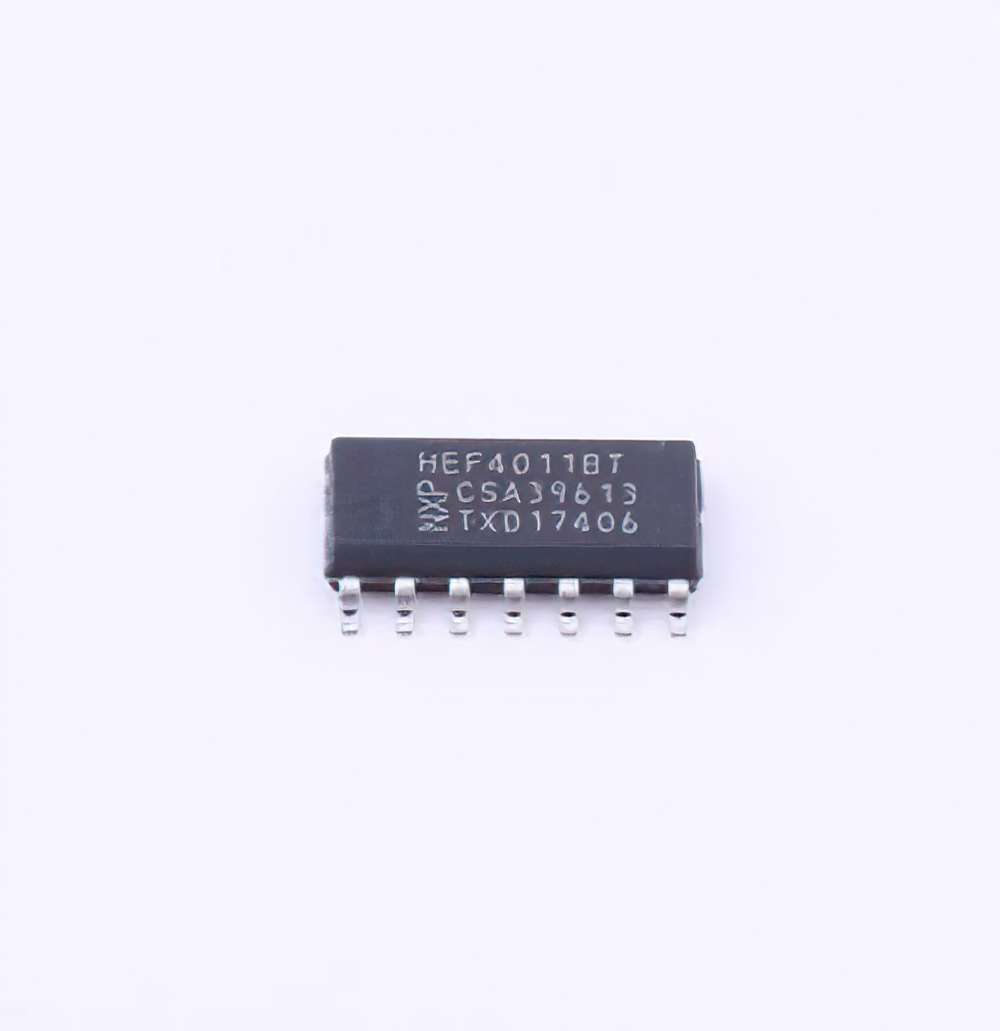
The HEF4011BT IC is a popular quad 2-input NAND gate chip that finds use in many digital electronics applications. Whether you're building complex circuits or experimenting with smaller designs, this IC plays a crucial role in logic operations. However, like any electronic component, the HEF4011BT is not immune to issues that may arise during operation. Understanding how to diagnose and resolve these problems is essential for ensuring your circuits work as expected.
What is the HEF4011BT IC?
The HEF4011BT is part of the 4000 series of CMOS (Complementary Metal-Oxide-S EMI conductor) logic gates. It features four independent 2-input NAND gates, making it an essential building block for constructing digital logic circuits. The device operates within a wide voltage range and offers low Power consumption, making it suitable for a broad range of applications in everything from basic circuit designs to more advanced microprocessor systems.
Key Features of HEF4011BT:
4 independent 2-input NAND gates
Low power consumption
Wide operating voltage range (3V to 15V)
CMOS technology for higher noise immunity
Standard 14-pin dual in-line package (DIP)
Despite its reliability, users can encounter a variety of issues when working with the HEF4011BT. Some of the most common problems include issues with power, signal integrity, incorrect logic output, and improper connections.
Common Troubleshooting Problems
Incorrect Logic Output
One of the most common issues with the HEF4011BT IC is incorrect logic output. Since the HEF4011BT is a logic gate, any error in the logic function can lead to unexpected circuit behavior. For instance, you may find that the NAND gates are not producing the expected high or low signals.
Cause:
This could be due to faulty connections, incorrect input logic, or damaged components that are not responding properly to voltage levels.
Solution:
Check the input pins for correct logic states. Use a multimeter or an oscilloscope to measure the voltage levels at the input and output pins to ensure that they conform to the expected logic levels.
Ensure that the power supply is providing the correct voltage and that the ground connections are solid.
Verify that the resistors and other components are within their rated tolerances and functioning properly.
Power Supply Issues
Power-related issues are another common problem when working with ICs like the HEF4011BT. If the IC does not receive sufficient or stable voltage, it may not operate correctly or even fail to function altogether.
Cause:
The HEF4011BT IC requires a steady supply voltage within the recommended range. If the supply voltage is too low or fluctuates, the IC might not perform as expected.
Solution:
Use a regulated power supply that can provide the required voltage. If you're using a battery, ensure it has enough charge to provide the necessary current. Also, check for any loose connections or bad solder joints in the power supply circuit.
Floating Inputs
Floating inputs are another common issue when working with digital ICs. When an input pin is not properly connected to a logic level (either high or low), it may "float" and pick up noise, leading to erratic behavior.
Cause:
Floating inputs can result from a missing connection or incorrect circuit design.
Solution:
Always ensure that unused input pins are tied to a defined logic level through pull-up or pull-down resistors. This prevents the inputs from floating and reduces the likelihood of noise or incorrect outputs.
Excessive Heat
Excessive heat can cause the HEF4011BT to malfunction or even get permanently damaged.
Cause:
Overheating can result from incorrect power supply voltage, high current draw, or poor thermal dissipation in the circuit.
Solution:
Ensure the IC is not drawing excessive current and that it is operating within the specified temperature range. If necessary, use a heat sink or improve the PCB design for better heat dissipation.
Incorrect Pin Connections
Improper pin connections can lead to logic errors or total circuit failure.
Cause:
Incorrectly connecting the IC pins is one of the most straightforward problems but can be easy to overlook, especially when working with a large number of components.
Solution:
Double-check the pinout of the HEF4011BT and confirm that each pin is correctly connected. It is advisable to refer to the datasheet for the exact pin configuration and to use a clear schematic diagram for your circuit.
Tools for Troubleshooting the HEF4011BT
Multimeter: A basic multimeter can help you check continuity, measure voltage, and assess the current in your circuit. It's useful for checking power connections and verifying voltage at different points.
Oscilloscope: An oscilloscope allows you to visualize the waveform of your digital signals, helping you identify timing issues or irregularities in logic output.
Logic Analyzer: For more complex troubleshooting, a logic analyzer can give you a detailed view of the digital signals on multiple channels. This tool is especially helpful for debugging complex circuits.
Test Circuit: When troubleshooting, consider building a simple test circuit with known inputs to isolate problems with the HEF4011BT.
Advanced Solutions and Preventative Measures for HEF4011BT Issues
Once you have an understanding of the basic troubleshooting techniques, it’s time to explore more advanced solutions and preventative measures that can help you avoid future problems with the HEF4011BT IC. These strategies include optimizing circuit design, using proper grounding techniques, and ensuring that the IC operates within its specified limits.
Advanced Solutions for Troubleshooting
Noise and Signal Integrity Issues
In digital circuits, signal integrity is critical for reliable operation. The HEF4011BT, like any CMOS IC, can be susceptible to noise, which can cause erratic behavior.
Cause:
The problem can arise from external electromagnetic interference (EMI), poor grounding, or long signal traces on a PCB.
Solution:
Implement proper decoupling capacitor s (typically 100nF) close to the power pins of the IC to filter out high-frequency noise.
Use short, direct traces for critical signal paths to minimize inductance and resistance.
Ensure a solid ground plane is used to provide a low-impedance path for return currents and reduce noise coupling.
Level Shifting Issues
If you are interfacing the HEF4011BT with other logic levels (e.g., 5V logic interfacing with 3.3V systems), level shifting becomes important to avoid improper voltage levels that could damage the IC.
Cause:
Directly connecting circuits with different voltage levels can cause unreliable behavior or permanent damage to the IC.
Solution:
Use level shifters or resistive voltage dividers to ensure that voltage levels are compatible between different parts of your circuit.
Some advanced ICs and MOSFETs are designed specifically for this purpose and can make level shifting more reliable.
Power Supply Noise
Power supply noise can adversely affect the performance of digital ICs, especially in high-speed applications.
Cause:
Fluctuations in the power supply or poor decoupling can introduce noise that interferes with the IC's operation.
Solution:
Use a low-pass filter on the power supply to reduce noise. A combination of capacitors (e.g., 10µF electrolytic capacitor in parallel with a 0.1µF ceramic capacitor) can help smooth out fluctuations.
Place the decoupling capacitors as close as possible to the power and ground pins of the HEF4011BT.
Temperature and Environmental Considerations
Temperature can significantly impact the performance of the HEF4011BT IC. If the operating environment is too hot or too cold, the IC may not function properly.
Cause:
Operating outside the specified temperature range or inadequate heat dissipation can cause the IC to become unreliable.
Solution:
Ensure that the HEF4011BT is placed in an environment with a temperature range within the recommended limits (typically -40°C to +85°C).
Use heat sinks, fans, or ensure sufficient ventilation in your circuit design to keep the IC cool.
Preventative Measures for Future Troubleshooting
Use of Proper Grounding Techniques
A common cause of issues in digital circuits is improper grounding. Poor grounding can introduce noise, cause signal degradation, and lead to logic errors.
Solution:
Ensure that all components share a common ground point and that the ground plane is as solid and uninterrupted as possible.
If your circuit is large, consider creating a star grounding scheme to minimize ground loops and reduce noise.
Design for Testing
Designing your circuit with troubleshooting in mind can save a lot of time when issues arise.
Solution:
Incorporate test points into your PCB design to make it easier to check voltages, signals, and other parameters during troubleshooting.
Ensure that components like the HEF4011BT are easily accessible for measurement and testing.
Use of Simulation Software
Before building your physical circuit, simulate the design using tools like SPICE or similar simulation software. This can help identify potential problems with the logic, power supply, or signal integrity before you assemble the hardware.
Solution:
Use simulation tools to verify the functionality of the HEF4011BT in your circuit. This will help you understand its behavior under different conditions and minimize errors during physical testing.
By following the troubleshooting and preventative measures outlined in this article, you can ensure that your HEF4011BT IC operates reliably, reducing the likelihood of errors and improving the overall performance of your digital circuits.
If you are looking for more information on commonly used Electronic Components Models or about Electronic Components Product Catalog datasheets, compile all purchasing and CAD information into one place.
Partnering with an electronic components supplier sets your team up for success, ensuring the design, production, and procurement processes are quality and error-free.


